Graphite fiber band stranding system

A graphite fiber and strand-making machine technology, which is applied in rope-making auxiliary devices, cable/conductor manufacturing, textiles and papermaking, etc., can solve the problems of low twisting efficiency and continuous production of strand-making machines, and improve twisting efficiency effect

Active Publication Date: 2019-10-25
XUCHANG SIDA ELECTRIC POWER EQUIP
View PDF12 Cites 0 Cited by
  • Summary
  • Abstract
  • Description
  • Claims
  • Application Information

AI Technical Summary

Problems solved by technology

[0004] The purpose of the present invention is to provide a graphite fiber tape stranding system to solve the technical problem that the stranding machine in the prior art cannot be continuously produced and the twisting efficiency is low

Method used


Image

  • Graphite fiber band stranding system
  • Graphite fiber band stranding system
  • Graphite fiber band stranding system

Examples


specific Embodiment

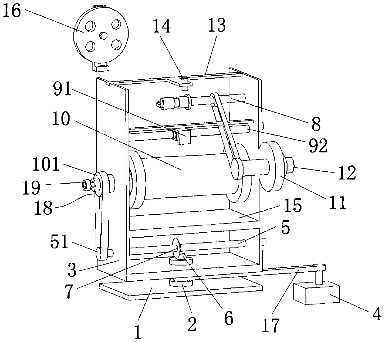
[0033] like Figure 1 to Figure 5 As shown, the graphite fiber tape strand-making system includes a strand-making machine and a material tray 16 located above the strand-making machine and spaced from the strand-making machine. The material tray 16 is wound with a strip-shaped graphite fiber ribbon during use. The material tray 16 is arranged by the mounting bracket when in use, and the strand making machine needs to rotate, and the graphite fiber strips released in the material tray 16 can be twisted to form graphite fiber lines by the relative rotation of the two. It should be noted that the arrangement of the material disc 16 referred to in the present invention means that the material disc 16 does not move or revolve as a whole, but the material disc 16 can rotate around its own axis.

[0034] It should be pointed out that there is still a large distance between the material tray 16 and the strand making machine, and a twisting cone will be arranged between the two (the tw...


PUM


Abstract

The invention relates to the technical field of graphite fiber band processing equipment, in particular to a graphite fiber band stranding system. The graphite fiber band stranding system comprises astranding machine and a material plate located above the stranding machine, wherein the stranding machine comprises a base, a central shaft and a main body support; an opening for allowing a graphitefiber thread to penetrate from top to bottom is formed in the upper end of the main body support; a driving mechanism can drive the main body support to rotate; a driving shaft is arranged on the mainbody support and can rotate around own axis; the upper end of the central shaft extends into the main body support, and a central shaft bevel gear is mounted at the upper end; a driving shaft bevel gear meshed with the central shaft bevel gear is arranged on the driving shaft; a winding bar is arranged on the main body support; when rotating with the main body support, the winding bar can twist graphite fiber bands which are discharged from the material plate and extend from top to bottom into graphite fiber threads; a winding reel is used for winding and collecting the graphite fiber lines passing the winding bar; the driving shaft is in transmission connection with the winding reel to drive the winding reel to wind and collect the graphite fiber lines.

Description

technical field [0001] The invention relates to the technical field of graphite fiber ribbon processing equipment, in particular to a graphite fiber ribbon strand-making system. Background technique [0002] When graphite fiber materials are applied to power transmission lines, graphite fiber tapes usually need to be converted into graphite fiber threads before they can be used. In the prior art, graphite fiber tapes are usually twisted by a strand-making machine to form graphite fiber threads. Specifically, first the graphite fiber tape is cut into strips, and the strip graphite fiber tape is wound on the material disc (similar to the film-like structure) to collect, and one end of the graphite fiber tape is wound on the take-up wheel, The take-up reel rotates around its own axis to pull the graphite fiber tape, rotates the material tray around the axis perpendicular to the take-up reel, twists the graphite fiber tape to form a graphite fiber thread, and then winds the grap...

Claims


Application Information

Patent Timeline
IPC IPC(8): D07B3/00D07B7/02D07B7/06D07B7/10H01B13/02
CPCD07B3/00D07B7/02D07B7/06D07B7/10H01B13/0235H01B13/0207
Inventor 张国锋胡松江陈瑞斌邢远朱义华陈见甫陈四甫赵振岭王治张明磊熊蕴曹岑杨小杰杨帆朱渊博王杰王倩倩邢丙师
Owner XUCHANG SIDA ELECTRIC POWER EQUIP
Why Eureka
Try Eureka