
Automobile engine oil recycling device and method

An engine oil recovery device and automobile technology, applied in garbage collection, household appliances, applications, etc., can solve problems such as improper recovery of waste engine oil, ineffective control of waste engine oil, and incomplete recycling of waste engine oil, etc., to achieve recycling safety , The effect of promoting green economic development

Pending Publication Date: 2019-10-25
广东新润环保技术研发有限公司
View PDF5 Cites 2 Cited by
  • Summary
  • Abstract
  • Description
  • Claims
  • Application Information

AI Technical Summary

Problems solved by technology

However, due to the lack of awareness and technology of most auto repair companies, and the lack of relevant research on pollution prevention and control in the auto repair industry, the auto repair industry has become a large producer of waste water, waste gas, and solid waste. Under the increasingly stringent environmental protection situation, Auto repair companies in many places were forced to rectify or even shut down
[0003] The more prominent one is the improper recycling of waste engine oil. The specific manifestation is that the waste engine oil replaced in the process of car maintenance has not been effectively controlled. Due to the mixed nature of the auto repair industry, some auto repair personnel use waste engine oil mixed with a small amount of waste in order to seek illegal benefits. The new engine oil is used for car maintenance, and the waste engine oil has not been completely recycled, which is not conducive to the healthy development of the market

Method used


Image

  • Automobile engine oil recycling device and method
  • Automobile engine oil recycling device and method

Examples


Embodiment Construction

[0024] The present invention will be further described below in conjunction with the accompanying drawings.

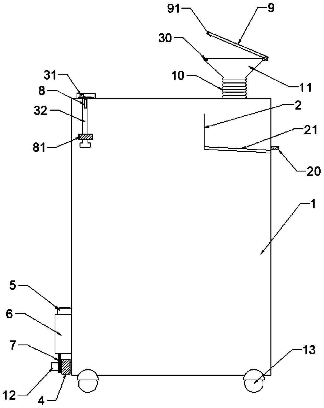
[0025] refer to figure 1 As shown, an automobile engine oil recovery device and method thereof has a recovery barrel 1, and an oil inlet 11 is arranged on the top of the recovery barrel 1. The automobile usually needs to be lifted to discharge waste engine oil, so the oil inlet 11 opens upward, and the oil inlet 11 The oil port 11 is preferably trumpet-shaped. The pulley 13 should be configured at the bottom of the recovery bucket 1, which can be easily moved to the bottom of the lifted car for oil recovery.

[0026] The oil inlet 11 is connected to the recovery barrel 1 through the telescopic tube 10, the telescopic tube 10 is preferably a snakeskin tube, and the oil inlet 11 can be stretched so as to be directly aligned with the oil shell at the bottom of the car for oil collection.

[0027] The upper part of the recovery barrel 1 is provided with a partition 2 and...


PUM


Abstract

The invention discloses an automobile engine oil recycling device and method. The automobile engine recycling device comprises a recycling barrel. The top of the recycling barrel is provided with an oil inlet, and the oil inlet is provided with an upper cover. The upper portion of the recycling barrel is provided with a partition layer and a liquid level alarming device. The liquid level alarmingdevice is linked with the upper cover. The partition layer is located under the oil inlet. A slag discharging groove is formed in the bottom of the partition layer, and an oil outlet is formed in thelower portion of the recycling barrel. An electromagnetic valve and an electronic flow meter which are connected with a circuit module are assembled at the position of the oil outlet, and a power source is used for supplying power to the electromagnetic valve, the electronic flow meter and the circuit module. The circuit module comprises a communication module conducting bidirectional signal transmission with a cloud server. A two-dimensional code is arranged on the recycling barrel for an APP end to scan and recognize, and the cloud server serves as a medium between the APP end and the communication module for bidirectional information transmission. Engine oil only enters the device but not exits from the device in the engine oil recycling process, people must hold an official account forscanning the two-dimensional code, the cloud server is used for starting the engine oil recycling device for fixed-point engine oil recycling, it is ensured that the engine oil is not secondarily used or discharged in a mess, and the automobile repairing market environment is purified.

Description

technical field [0001] The invention belongs to the technical field of auto repair waste oil recovery, and in particular relates to an automobile engine oil recovery device and a method thereof. Background technique [0002] With the development of economy and society, automobiles have become an indispensable means of transportation in daily life. With the increasing number of automobiles, the auto repair industry is booming. However, due to the lack of awareness and technology of most auto repair companies, and the lack of relevant research on pollution prevention and control in the auto repair industry, the auto repair industry has become a large producer of waste water, waste gas, and solid waste. Under the increasingly stringent environmental protection situation, Auto repair companies in many places were forced to rectify or even shut down. [0003] The more prominent one is the improper recycling of waste engine oil. The specific manifestation is that the waste engine...

Claims


Application Information

Patent Timeline
IPC IPC(8): B65F1/14B65F1/12
CPCB65F1/14B65F1/12B65F2210/168B65F2210/182B65F2210/108B65F2210/128B65F2240/152
Inventor 朱锡勇朱锡鑫林培钟
Owner 广东新润环保技术研发有限公司
Learn More