Hole inner wall wear-resistant layer preparation method capable of increasing product percent of pass

A technology of product pass rate and wear-resistant layer, which is applied in the field of nuclear power plant control rod drive mechanism parts manufacturing, can solve problems such as low pass rate, achieve the effects of improving product pass rate, realizing batch production, and benefiting welding quality

Pending Publication Date: 2019-10-25
喻杰
View PDF1 Cites 2 Cited by
  • Summary
  • Abstract
  • Description
  • Claims
  • Application Information

AI Technical Summary

Problems solved by technology

[0006] Aiming at the technical problem of low pass rate in the preparation of the existing surfacing hooks proposed above, the present invention provides a method for preparing the wear-resistant layer on the inner wall of the hole that can improve the pass rate of the product

Method used


Image

  • Hole inner wall wear-resistant layer preparation method capable of increasing product percent of pass
  • Hole inner wall wear-resistant layer preparation method capable of increasing product percent of pass
  • Hole inner wall wear-resistant layer preparation method capable of increasing product percent of pass

Examples


Embodiment 1

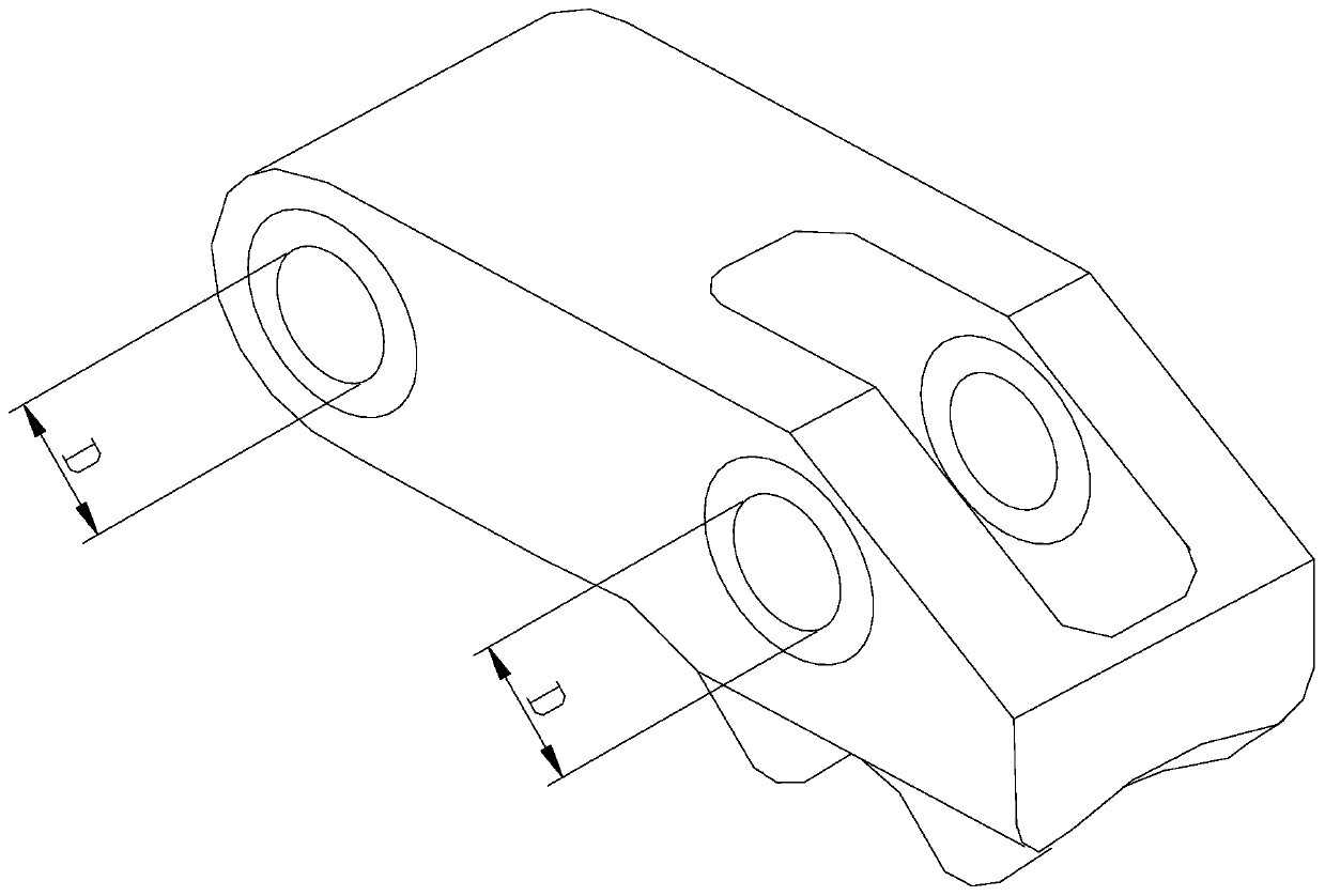
[0043] Such as Figure 3 to Figure 7 As shown, a method for preparing the wear-resistant layer on the inner wall of the hole that can improve the product qualification rate is used to obtain a wear-resistant layer on the surface of the prefabricated hole 6 of the part 5, and finally obtain a wear-resistant layer on the part 5 with an inner diameter of D and a wear-resistant hole wall. Layer holes, including the following steps:

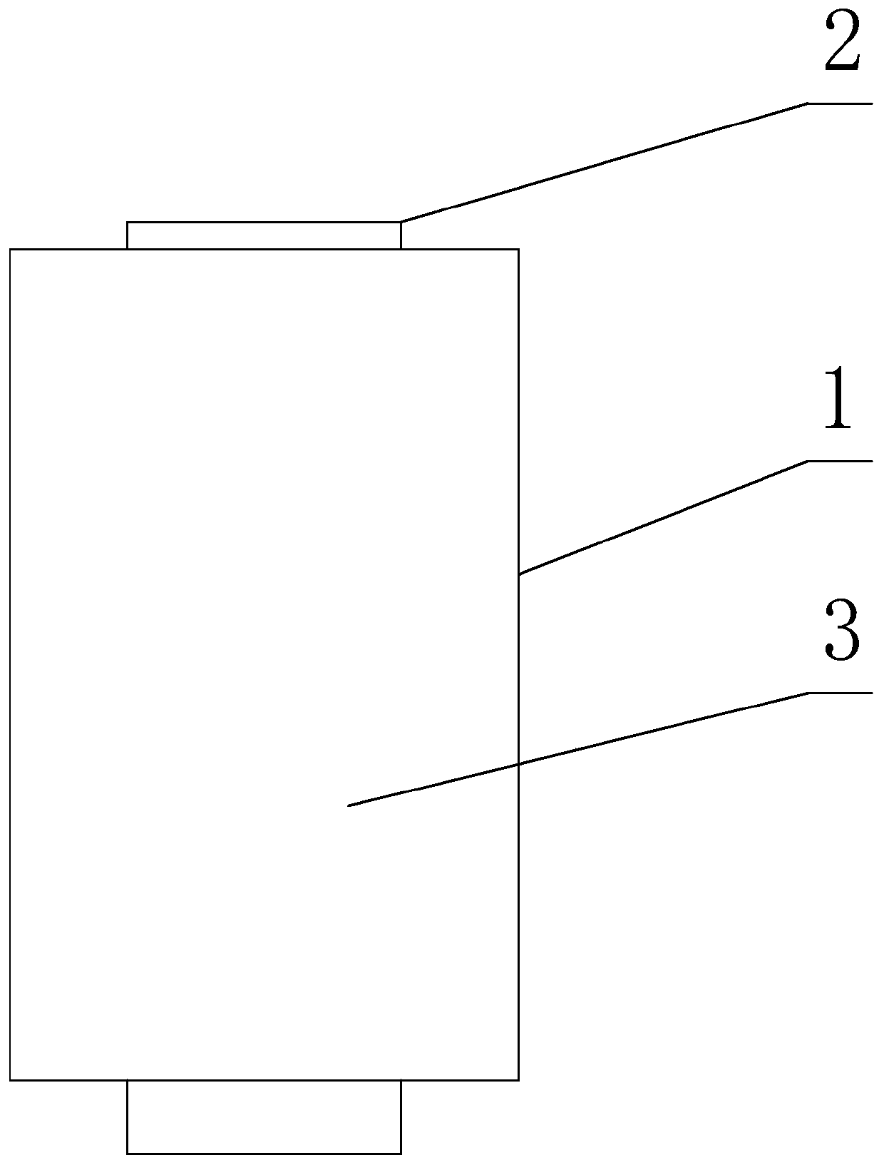
[0044] S1. Drill a prefabricated hole 6 with an inner diameter of D1 on the part 5, where D1>D; obtain a filler rod 1 for welding, the outer diameter of the filler rod 1 is smaller than D1 and larger than D;

[0045] S2. Insert the filling mandrel 1 into the prefabricated hole 6, and fill the gap 7 between the filling mandrel 1 and the prefabricated hole 6 by filling welding or self-fusion welding;

[0046] S3. A hole with a diameter of D is obtained on the filling mandrel 1, and the filling mandrel 1 provides all hole walls for the hole with a diame...

Embodiment 2

[0054] This embodiment is further limited on the basis of Embodiment 1. As a specific implementation, it is set as follows: the filling mandrel 1 is a hollow rod with a central hole;

[0055] The outer diameter D2 of the filling mandrel 1 satisfies the following relationship: D1>D2>D, the central hole diameter D3 is: D3≤D, and the material of the filling mandrel 1 is consistent with that of the wear-resistant layer. In this solution, the filling mandrel 1 is arranged in a tubular shape, the filling mandrel 1 is inserted into the prefabricated hole 6 and filled and welded, and then the final hole is obtained on the filling mandrel 1 . Adopting this scheme facilitates the final hole processing.

Embodiment 3

[0057] The present embodiment is further limited on the basis of Embodiment 1. As mentioned above, since the filling mandrel 1 needs to be filled and welded after being embedded in the prefabricated hole 6, in order to eliminate the surface layer of the center hole of the filling mandrel 1 to facilitate the quality of the hole wall, It is set as follows: said D3


PUM


Abstract

The invention discloses a hole inner wall wear-resistant layer preparation method capable of increasing the product percent of pass. The method is used for obtaining a wear-resistant layer on the surface of a part pre-formed hole and finally obtaining a hole, having the inner diameter D and comprising the hole wall wear-resistant layer, on a part. The hole inner wall wear-resistant layer preparation method includes the following steps that S1, the pre-formed hole with the inner diameter D1 is drilled on the part, wherein D1 is larger than D; a filling core rod used for welding is obtained, andthe outer diameter of the filling core rod is smaller than D1 and larger than D; S2, the filling core rod is embedded in the pre-formed hole, and the gap between the filling core rod and the pre-formed hole is filled up through filling welding or self-fluxing welding; S3, a hole with the hole diameter D is obtained on the filling core rod, the filling core rod provides the whole hole wall for thehole with the hole diameter D, and the material of the filling core rod is the material of the wear-resistant layer. Due to the adoption of the method, the build-up welding difficulty of a hole innerwall build-up welding layer can be effectively lowered, and the aims of ensuring the build-up welding quality of the build-up welding layer and increasing the product percent of pass are achieved.

Description

technical field [0001] The invention relates to the technical field of manufacturing parts of a control rod driving mechanism of a nuclear power plant, in particular to a method for preparing a wear-resistant layer on an inner wall of a hole, which can improve the qualified rate of products. Background technique [0002] Reactor Control Rod Drive Mechanism (CRDM) is one of the key equipment in nuclear power plants. Its principle can be: by controlling the regular changes of the electromagnetic field to drive the claw parts to produce corresponding actions, thereby driving the drive rod parts and then driving the control rod components in the reactor The core moves up and down to realize a series of important functions such as starting and stopping the reactor, adjusting or maintaining the core power during normal operation and rapid shutdown under accident conditions. [0003] For the CRDM used in nuclear power plants including claws in active service, each set contains two ...

Claims


Application Information

Patent Timeline
Patent Type & Authority Applications(China)
IPC IPC(8): B23P17/00
CPCB23P17/00G21C7/12G21C13/036G21C21/18Y02E30/30
Inventor 喻杰
Owner 喻杰
Why Eureka
Try Eureka