
Electric thruster anode gas distributor

An anode gas and electric thruster technology, applied in the field of electric propulsion, can solve problems such as uneven environment of neutral particles in the discharge channel, decreased efficiency of electric thrusters, intensified electron flow, etc., achieve good structural strength and anti-vibration performance, reduce The effect of complexity, simple structure and stability

Active Publication Date: 2019-10-22
BEIHANG UNIV
View PDF6 Cites 6 Cited by
  • Summary
  • Abstract
  • Description
  • Claims
  • Application Information

AI Technical Summary

Problems solved by technology

The miniaturization of the electric thruster makes the size of the discharge channel smaller, which brings difficulties to the design of the anode gas distributor
The aerodynamic design of the traditional multi-hole electric thruster gas distributor will make the circumferential and radial distribution of the propellant gas in the discharge channel uneven, resulting in a much higher density of the propellant gas near the outlet of the intake pipe than in other areas. This makes the neutral particle environment in the discharge channel uneven, the plasma discharge is uneven, and the flow of electrons to the anode is intensified, resulting in a decline in the efficiency of the electric thruster

Method used


Image

  • Electric thruster anode gas distributor
  • Electric thruster anode gas distributor
  • Electric thruster anode gas distributor

Examples


Embodiment Construction

[0034] In order to understand the above-mentioned purpose, features and advantages of the present invention more clearly, the present invention will be further described in detail below in conjunction with the accompanying drawings and specific embodiments. It should be noted that, in the case of no conflict, the embodiments of the present invention and the features in the embodiments can be combined with each other.

[0035] In the following description, many specific details are set forth in order to fully understand the present invention. However, the present invention can also be implemented in other ways different from those described here. Therefore, the protection scope of the present invention is not limited by the specific details disclosed below. EXAMPLE LIMITATIONS.

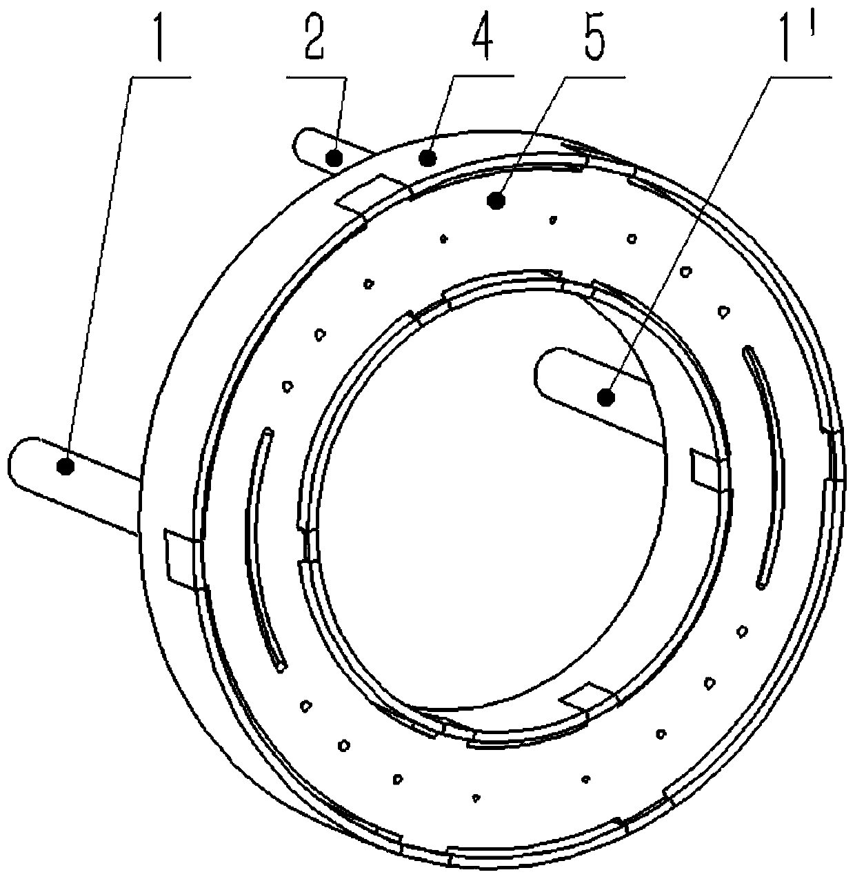
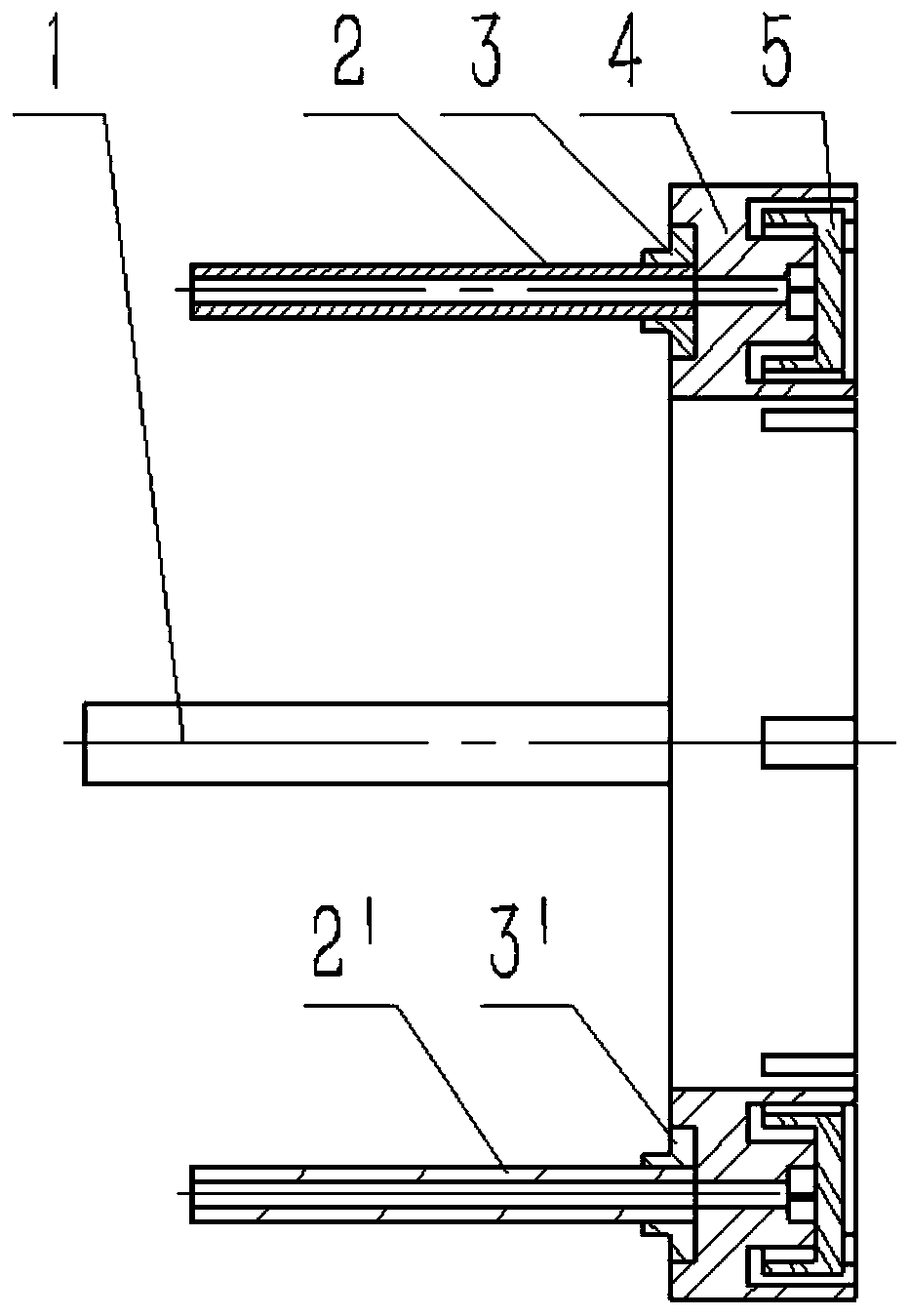
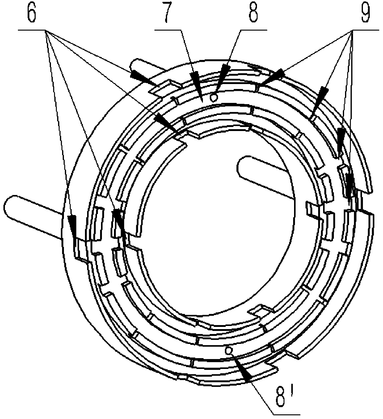
[0036] Such as Figure 1-Figure 5 As shown, an electric thruster anode gas distributor according to an embodiment of the present invention is characterized in that it includes a first welding screw 1,...


PUM


Abstract

The invention discloses an electric thruster gas distributor. The electric thruster gas distributor comprises a first welding screw, a second welding screw, a first gas inlet pipe, a second gas inletpipe, a first gas inlet pipe fixing seat, a second gas inlet pipe fixing seat, a distributor lower bottom and a distributor upper bottom, wherein a plurality of pairs of fixing key grooves, a circumferential gas conveying groove, a first gas inlet hole, a second gas inlet hole, a first counter bore, a second counter bore and radial gas conveying grooves are formed in the inner circumference and the outer circumference of the distributor lower bottom; and fixing keys corresponding to the plurality of pairs of fixing key grooves, a 0.32 mm jet hole, a 0.46 mm jet hole, a 0.56 mm jet hole, a 0.6mm jet slit and a 1 mm flow blocking plate are arranged on the inner circumference and the outer circumference of the distributor upper bottom. According to the technical scheme of the electric thruster gas distributor, the distribution of the gas flow can be controlled so as to achieve more uniform gas distribution, and a uniform and stable neutral particle environment is provided for an electricthruster.

Description

technical field [0001] The invention belongs to the technical field of electric propulsion, in particular to an electric thruster gas distributor. Background technique [0002] Due to its advantages of high specific impulse, long life, and small size, electric propulsion technology has been more and more widely used in space activities. With the development of microsatellites in recent years, small electric thrusters have gradually developed. The miniaturization of the electric thruster makes the size of the discharge channel smaller, which brings difficulties to the design of the anode gas distributor. The aerodynamic design of the traditional multi-hole electric thruster gas distributor will make the circumferential and radial distribution of the propellant gas in the discharge channel uneven, resulting in a much higher density of the propellant gas near the outlet of the intake pipe than in other areas. This makes the neutral particle environment in the discharge channe...

Claims


Application Information

Patent Timeline
Patent Type & Authority Applications(China)
IPC IPC(8): F03H1/00
CPCF03H1/0012
Inventor 汤海滨刘一泽张广川章喆王一白任军学
Owner BEIHANG UNIV
Learn More