An automatic rope erection system between tall buildings

A technology of high-rise buildings and ropes, applied in life-saving equipment, building rescue, etc., to achieve the effect of efficient and safe reciprocating motion

Active Publication Date: 2020-09-04
CIVIL AVIATION UNIV OF CHINA
View PDF10 Cites 2 Cited by
  • Summary
  • Abstract
  • Description
  • Claims
  • Application Information

AI Technical Summary

Problems solved by technology

[0004] The purpose of the present invention is to provide an automatic rope erection system between high buildings to solve the problem of safely, economically and efficiently erecting reciprocating ropes between the roofs of two high buildings

Method used


Image

  • An automatic rope erection system between tall buildings
  • An automatic rope erection system between tall buildings
  • An automatic rope erection system between tall buildings

Examples


Embodiment Construction

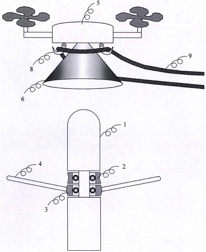
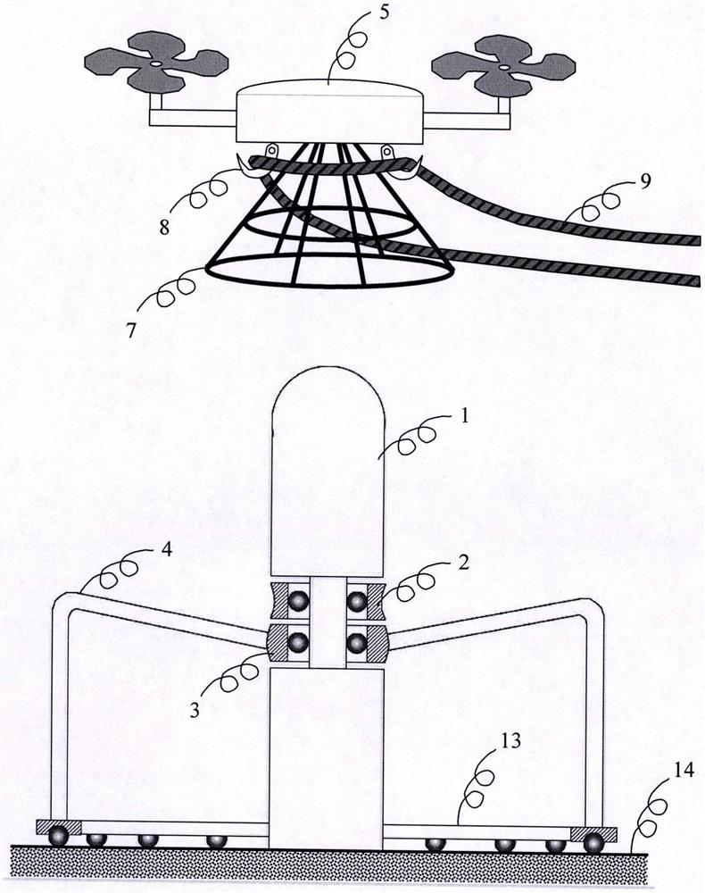
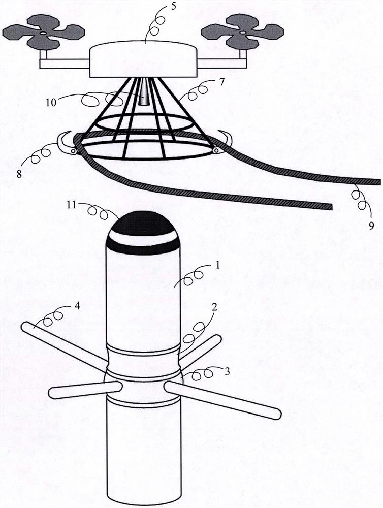
[0019] Below in conjunction with accompanying drawing, a kind of automatic rope erecting system among tall buildings of the present invention is described further. Explanation of numbers in the accompanying drawings: 1 column 2 pulley 3 swivel 4 spoke 5 helical wing drone 6 solid surface horn-shaped guide rail 7 mesh horn-shaped guide rail 8 hook 9 rope 10 camera 11 positioning icon 12 straight tube-shaped horn root 13 base The top ground of the 14th floor of the swivel.

[0020] figure 1A structural diagram of an automatic rope erection system between tall buildings of the present invention is given. The column (1) is installed on the roof of a high-rise building. The top of the column (1) is smooth and blunt. A pulley (2) is nested near the middle of the column (1). The diameter of the outer ring of the pulley (2) is slightly smaller than that of the column ( 1) diameter; a swivel (3) is nested on the column (1) next to the pulley (2), and the swivel (3) can rotate around ...


PUM


Abstract

The invention discloses an automatic rope erecting system between tall buildings. The system aims at achieving automatic erecting of a rope capable of doing reciprocated motion between roofs of two tall buildings. The system comprises stand columns on the roofs and an unmanned aerial vehicle for conveying the rope, the tops of the stand columns are in smooth blunt tip shapes, the middle of each stand column is sleeved with a pulley, the outer ring of the pulleys is slightly smaller than the diameter of the stand columns, a trumpet-shaped guide rail is arranged on the lower face of an unmannedaerial vehicle body, and is used for guiding the unmanned aerial vehicle to hover above the stand columns, a ring of hooks are arranged on the lower face of the unmanned aerial vehicle body in a manner of surrounding the trumpet-shaped guide rail, the rope required to be erected is hung on the hooks around the trumpet-shaped guide rail, after the rope is hung, the hooks are put away to ensure thatthe rope cannot fall off from the unmanned aerial vehicle in the conveying process, after the unmanned aerial vehicle hovers above the stand columns, the hooks are opened to enable a rope sleeve to fall to sleeve the stand columns, and the rope sleeve further slides to sleeve the pulleys of the lower ends of the stand columns. The erected rope can do reciprocation motion around the pulleys, and the rope can conveniently convey the persons and goods and materials in a reciprocated manner between the roofs of the tall buildings.

Description

Technical field: [0001] The invention provides an automatic rope erection system between tall buildings, which belongs to the field of safety science and engineering. Background technique: [0002] As the economy continues to develop and high-rise buildings continue to increase, the disaster risks associated with high-rise buildings, such as fire risks, are also increasing. When a high-rise fire occurs, a rope is erected between the roof of the fire high-rise building and the roof of the adjacent safe high-rise building to transport personnel and materials, which can play a positive role in the rescue of high-rise fires. Under normal circumstances, permanent ropes are not erected between the roofs of high-rise buildings, because permanently erected ropes are exposed to rain and sun for a long time, difficult to maintain, difficult to overhaul, and cannot be used safely during disaster rescue. Therefore, it is generally necessary to temporarily set up ropes between the roofs...

Claims


Application Information

Patent Timeline
Patent Type & Authority Patents(China)
IPC IPC(8): A62B1/06A62B1/18
CPCA62B1/06A62B1/18
Inventor 胡小兵廖建勤
Owner CIVIL AVIATION UNIV OF CHINA
Why Eureka
Try Eureka