Cloth roller transmission device of friction-free cloth rolling machine

A technology of a transmission device and a cloth rolling roller, which is applied in the field of the cloth winding roller transmission device of a cloth winding machine, and can solve problems such as difficulty in controlling the tension of the winding cloth roll, the short service life of the transmission belt 50, and frequent maintenance

Inactive Publication Date: 2012-01-25
QUANZHOU LUOJIANG YONGTAI MACHINERY
View PDF6 Cites 1 Cited by
  • Summary
  • Abstract
  • Description
  • Claims
  • Application Information

AI Technical Summary

Problems solved by technology

Since the cloth roll 11 is rotating at a constant speed, the outer diameter of the cloth roll rolled up on the cloth roll 11 is continuously increasing, and the lower cloth speed of the pulling shaft group 12 is also kept constant. When there is a difference between the speed and the lower cloth speed of the pulling shaft group 12, the cloth winding roller 11 is restrained by the lower cloth speed, and the winding speed of the cloth winding roller 11 can only be adjusted by the friction and slip of the transmission belt 50 to keep the lower cloth and the cloth rolling Consistency, so, the larger the cloth volume that the cloth roll roller 11 rewinds, the more severe the friction and slippage of the transmission belt 50, and the faster the wear and tear, resulting in the short service life of the transmission belt 50, frequent maintenance, and it is difficult to control the cloth in the process of rewinding the cloth. Roll tension, affecting the quality of cloth

Method used


Image

  • Cloth roller transmission device of friction-free cloth rolling machine
  • Cloth roller transmission device of friction-free cloth rolling machine
  • Cloth roller transmission device of friction-free cloth rolling machine

Examples


Embodiment Construction

[0017] Below in conjunction with accompanying drawing, the present invention is described in further detail:

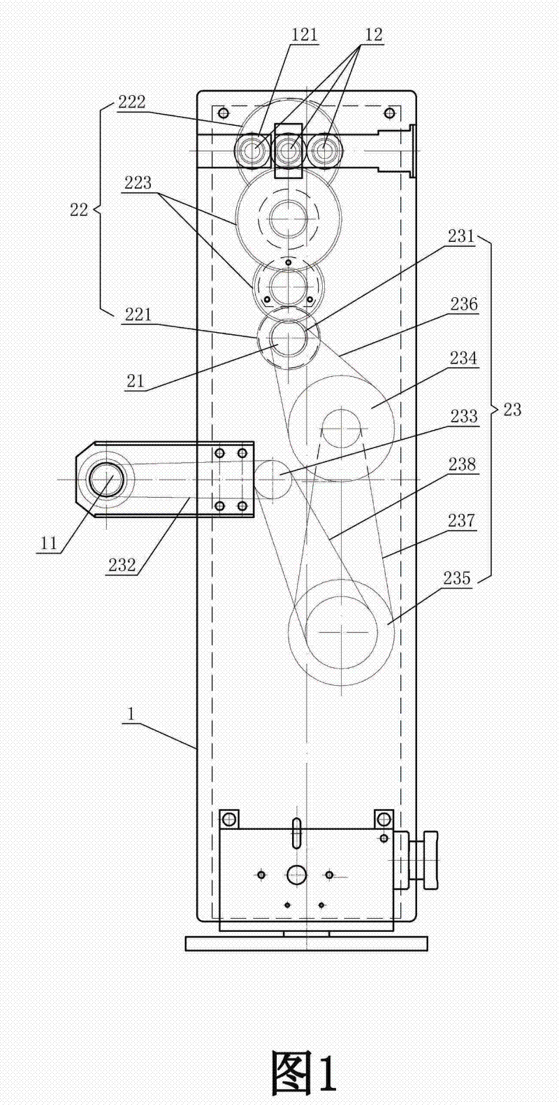
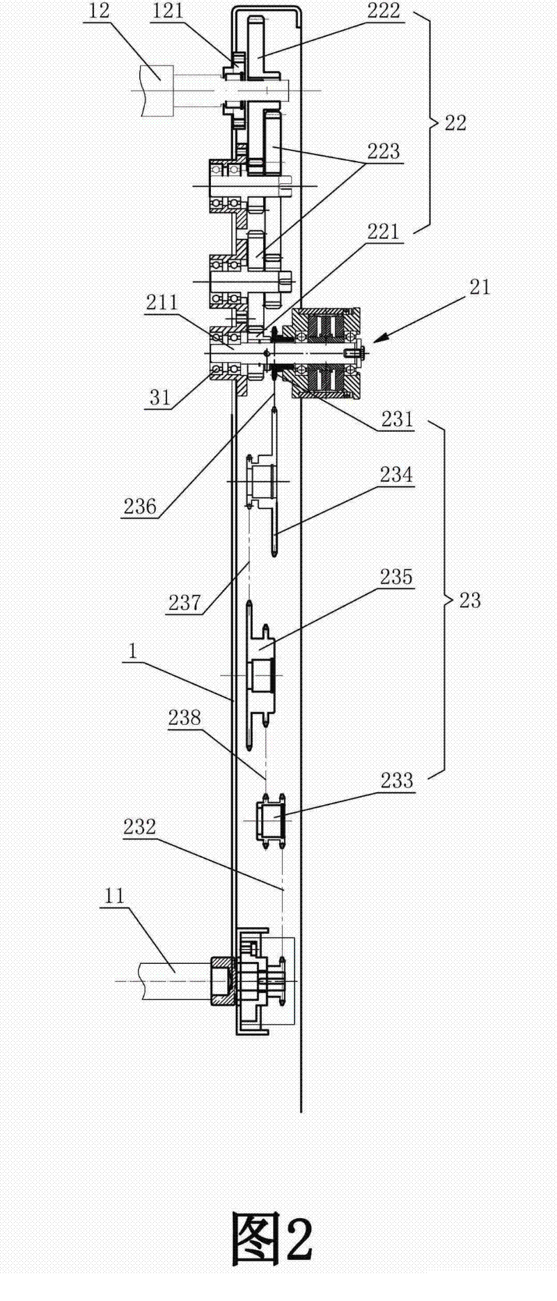
[0018] refer to figure 1 and figure 2 . A non-friction cloth rolling machine transmission device, including a base, a variable speed transmission box, and a slewing frame with side casings on both sides correspondingly. Cloth pulling shaft group 12, cloth rolling roller 11 is arranged in the front; cloth pulling shaft group 12 is connected with the power output shaft of the speed change transmission box through the transmission assembly installed in one side of the chassis, and cloth rolling roller 11 is installed in the other The transmission mechanism in one side of the cabinet 1 is connected to the pull shaft group 12 in transmission, and the shaft ends of each pull shaft of the pull shaft group 12 in the side cabinet 1 are equipped with transmission gears 121 for mutual meshing transmission (not shown in the figure). Shows the base, the variable speed transmi...


PUM


Abstract

The invention relates to a cloth roller transmission device of a friction-free cloth rolling machine, which comprises a base, a transmission case and a reversing frame with two sides being correspondingly and respectively provided with a side case. A cloth pulling shaft set is arranged at the top of the two side cases, and a cloth roller is arranged at the front of the two side cases. The cloth roller is connected with the cloth pulling shaft set in a driving way through a transmission mechanism which is installed in one side case. The transmission mechanism comprises a permanent magnet tension controller which is provided with a power input shaft and a power output shaft, a first transmission assembly which is arranged between the power input shaft of the permanent magnet tension controller and the cloth pulling shaft set, and a second transmission assembly which is arranged between the power output shaft of the permanent magnet tension controller and the cloth roller. By using the permanent magnet tension controller which transfers constant torque force by using a magnetic field as a medium, the cloth roller transmission device of the friction-free cloth rolling machine has the advantages that the friction-free transmission is realized, the output torque force is convenient to adjust, the service life of the transmission mechanism is greatly prolonged, the magnitudes of internal tension and external tension of rolled cloth are consistent, and the quality of the cloth is improved.

Description

technical field [0001] The invention relates to the technical field of transmission of a cloth roll of a cloth winding machine, in particular to a frictionless transmission device for the cloth winding roller of a cloth winding machine. Background technique [0002] From Figure 5 It can be seen from the figure that the general structure of the existing cloth rolling machine is to include a base, a speed change transmission box installed on the base, two sides are correspondingly provided with a left side chassis 1, a swivel frame of the right side chassis, and a cloth rolling roller 11 (The base, the variable speed transmission box and the right side chassis of the slewing frame are not shown in the figure), and the cloth shaft composed of three parallel shafts that mesh with each other is erected between the top of the left side case 1 and the right side case. Shaft group 12; one side of the variable speed transmission box is connected with a transmission shaft to the righ...

Claims


Application Information

Patent Timeline
IPC IPC(8): B65H79/00
Inventor 涂明招
Owner QUANZHOU LUOJIANG YONGTAI MACHINERY
Why Eureka
Try Eureka