
Energy-saving environment-friendly safety mower

A kind of technology of energy saving and environmental protection, lawn mower

Active Publication Date: 2019-10-22
ZHEJIANG CHANGJIANG MACHINERY
View PDF6 Cites 1 Cited by
  • Summary
  • Abstract
  • Description
  • Claims
  • Application Information

AI Technical Summary

Problems solved by technology

[0005] The purpose of the present invention is to provide an energy-saving and environment-friendly safe lawnmower capable of automatically displaying the working edge in view of the inconvenient judgment of the working edge of the existing lawnmower body, which is likely to cause accidents and increase the difficulty of operation

Method used


Image

  • Energy-saving environment-friendly safety mower
  • Energy-saving environment-friendly safety mower
  • Energy-saving environment-friendly safety mower

Examples


Embodiment 1

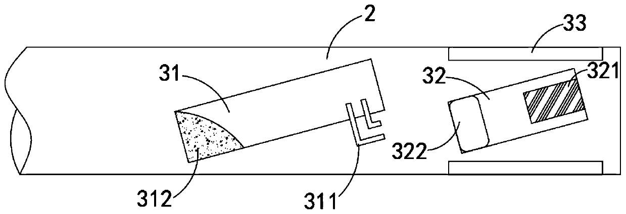
[0023] Such as Figure 1-3 As shown, an energy-saving and environment-friendly safe mowing machine includes a mowing machine body 1, a mowing rope 2 is installed on both sides of the lower end of the mowing machine body 1, and a warning mechanism 3 is provided at the end of the mowing rope 2, The warning mechanism 3 includes a control tube 31 and a power generation tube 32 which are obliquely arranged in the mower rope 2. The control tube 31 and the power generation tube 32 are arranged at an angle of 15°-18° relative to the vertical plane of the mower body 1 axis. The upper and lower end faces of 2 are all embedded with LED light sheet 33, and the LED light sheet 33 is arranged near the edge of the mowing rope 2, and the LED light sheet 33 emits a striking red light, and the LED light sheet 33, the power generation tube 32 and the control tube 31 couplings form a closed loop in series.

[0024] Two conductive columns 311 are embedded on the lower side wall of the upper end o...

Embodiment 2

[0029] Such as Figure 4-5 As shown, the difference between this embodiment and Embodiment 1 is that the extrusion block 322 is in sliding and sealing connection with the inner side wall of the power generation tube 32, and the bottom of the power generation tube 32 is provided with a pressure stabilizing hole 323 communicating with the outside, which can maintain power generation. The internal and external pressure of the pipe 32 is balanced, and the end of the mowing rope 2 is fixedly connected with an elastic airbag 34 that can extend axially along the mowing rope 2.

[0030] In this embodiment, when the extrusion block 322 moves upward, the air in the power generation tube 32 will be squeezed into the elastic air bag 34 along the air delivery channel 341, which greatly improves the cushioning at the edge of the mowing rope 2. The effect is to further improve the safety of the mower 1 during use. When the mower 1 stops working, the extrusion block 322 and the elastic air ba...


PUM


Abstract

The invention belongs to the field of energy conservation and environmental protection and particularly relates to an energy-saving environment-friendly safety mower, comprising a mower body. A mowingrope is fitted to each side of the lower end of the mower body; the tail end of each mowing rope is provided with a warning mechanism; each warning mechanism comprises a control tube and a power generation tube both arranged obliquely inside one mowing rope; an LED sheet is embedded in each of the upper and lower ends of each mowing rope; the LED sheets, the corresponding power generation tube and the corresponding control tube are coupled to form a series closed loop. The control tubes, the power generation tubes and the LED sheets are provided; when the mowing ropes rotate to a certain speed, the power generation tubes can be triggered to generate electricity, the control tubes are switched on, and the LED sheets emit light; the edge of each cutting wheel formed by the rotation of one mowing rope forms a visual warning ring, so that it is convenient for operators to see the edge of the mowing rope, the mower body can be controlled better, and damage to the mower body and other objects on a lawn is decreased.

Description

technical field [0001] The invention belongs to the field of energy saving and environmental protection, and in particular relates to an energy saving and environment-friendly safe mowing machine. Background technique [0002] The mower body is a hand-held lawn trimming tool used for trimming the lawn. The mower body is generally composed of a grip lever, a connector, a motor, a rotating disc and a mowing rope. The motor is used to drive the rotating disc. Rotate to make the mowing rope rotate rapidly to form an annular cutting wheel to cut the grass stems and keep the turf at the same height. [0003] When the existing mowing rope reaches a certain speed, the boundary of its rotation is relatively vague, especially in the process of operation, it is inconvenient for the staff to stop and observe carefully, so they can only operate by feeling; There are also obstacles such as fire hydrants and shrubs, so when building the grass around the above-mentioned obstacles, it is ea...

Claims


Application Information

Patent Timeline
IPC IPC(8): A01D34/416G09F13/22
CPCA01D34/416A01D34/4167G09F13/22G09F2013/222
Inventor 赵婷婷
Owner ZHEJIANG CHANGJIANG MACHINERY
Learn More