
Device for supplying electric energy to wave glider

A glider and wave technology, applied in the direction of electromechanical devices, propulsion device engines, electrical components, etc., can solve problems such as solar panel damage, platforms can not continue to work, battery packs can not be charged in time, and achieve simple installation and energy utilization efficiency High and long service life effect

Inactive Publication Date: 2019-10-18
SHENZHEN INVESTMENT HLDG CO LTD +1
View PDF6 Cites 5 Cited by
  • Summary
  • Abstract
  • Description
  • Claims
  • Application Information

AI Technical Summary

Problems solved by technology

The current wave glider uses solar power generation technology to power various sensors and power systems on the platform. However, when solar panels are used to collect solar energy to power the entire platform system, it will cause serious damage in rainy weather and extreme sea conditions. The solar panel does not charge the battery pack in time and the solar panel is damaged, so the platform cannot continue to work; while wave power generation (Wave Power Generation) uses the energy of waves as the power to generate electricity, because the wave glider has its unique ability to go up and down with the waves. The existence of the undulating movement mode and the effective use of wave energy for power generation have great significance for the stable operation of the wave glider power system

Method used


Image

  • Device for supplying electric energy to wave glider
  • Device for supplying electric energy to wave glider

Examples


Embodiment Construction

[0018] The present invention will be described in further detail below in conjunction with the accompanying drawings and specific embodiments. It should be understood that the specific embodiments described here are only used to explain the present invention, not to limit the present invention.

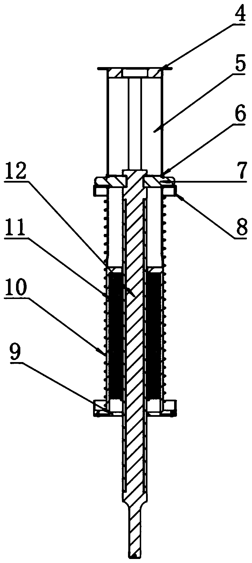
[0019] Such as figure 1 and figure 2 As shown, a device for supplying electric energy of a wave glider includes three parts: a wave glider floating body ship 1, a generator body 2 and a wave glider tractor 3; the generator body includes: a generator housing 5, a magnet rod 12, Card lock 7, card lock collar 6, casing upper cover 4, casing lower cover 9, coil 11, spring 10, spring baffle 8;

[0020] The upper cover plate 4 of the casing is connected with the bottom of the wave glider floating body boat 1 through screws, the generator casing 5 is connected with the upper cover plate 4 of the casing through screws, and the lock collar 6 is placed on the lock 7, and one end It is fixed...


PUM


Abstract

The invention discloses a device for supplying electric energy to a wave glider. The device comprises a floating boat, a generator body and a tractor. The generator body is in rigid connection with the floating boat and the tractor. The floating boat and the tractor vertically move to drive a magnet bar and coils in the generator body to conduct magnetic induction line cutting motion, and then power is generated. The device has the advantages that the generator body ascends and descends along with the floating boat and the tractor, the magnet bar and the coils conduct relative motion all the time, then the reliability of a power generating device is guaranteed, and the motion mode of the wave slider is reasonably utilized for power generation. In the power generating process of the device,all the coils are sealed in a pouring sealant, the sealing performance is good, and the service life is long. The generator body of the device replaces an original method that an armored cable is utilized for connecting the floating boat and the tractor together, and the problem that due to the fact that the armored cable is destroyed in an extreme offshore environment, communication between thefloating boat and the tractor is interrupted, and equipment faults are caused is avoided.

Description

technical field [0001] The invention relates to a wave energy generating device of a wave glider, in particular to a device for supplying electric energy of the wave glider. Background technique [0002] At present, the rise of marine mobile observation platforms has brought great convenience to the collection of various data such as climate on the ocean. The wave glider has the advantages of long voyage time, long voyage distance, and no need for traditional propulsion methods. A new type of ocean observation platform. [0003] However, since the sea area where the wave glider works is far away from the offshore station, the normal use of the power system responsible for power supply is a prerequisite for ensuring the normal use of the platform. The current wave glider uses solar power generation technology to power various sensors and power systems on the platform. However, when solar panels are used to collect solar energy to power the entire platform system, it will cau...

Claims


Application Information

Patent Timeline
IPC IPC(8): F03B13/20B63H21/17H02K5/10
CPCB63H21/17F03B13/20H02K5/10Y02E10/30
Inventor 桑宏强刘芬关海鹏游雨嵩张帅彭彬何柏岩杨绍琼
Owner SHENZHEN INVESTMENT HLDG CO LTD
Learn More