
Electrolytic cell temperature regulating and controlling device and regulating and controlling method

A control device and electrolytic cell technology, which is applied in the field of chemical industry equipment, can solve the problems of low temperature detection accuracy, long measurement cycle, and large consumption of thermocouples, etc., to reduce heat dissipation speed, reduce manual labor, and reduce energy consumption. Effect

Inactive Publication Date: 2019-10-18
陈雨
View PDF5 Cites 0 Cited by
  • Summary
  • Abstract
  • Description
  • Claims
  • Application Information

AI Technical Summary

Problems solved by technology

Basically, each electrolytic cell only measures the temperature once a day. This method is time-consuming and laborious, the measurement cycle is long, and it is all offline data, which has hysteresis; there is also a method of measuring the electrolyte temperature using a hand-held temperature measuring device. Although the measurement data can be transmitted to the slot control machine in time, manual operation is also required
Both of the above two methods need to use a thermocouple to be inserted into the electrolytic cell. After a period of time, the consumption of the thermocouple is also very large, resulting in low temperature detection accuracy, and it is impossible to adjust the temperature in the electrolytic cell in real time. Electrolysis efficiency

Method used


Image

  • Electrolytic cell temperature regulating and controlling device and regulating and controlling method
  • Electrolytic cell temperature regulating and controlling device and regulating and controlling method
  • Electrolytic cell temperature regulating and controlling device and regulating and controlling method

Examples


Embodiment Construction

[0030] In order to make the object, technical solution and advantages of the present invention clearer, the present invention will be further described in detail below in conjunction with the accompanying drawings and embodiments. It should be understood that the specific embodiments described here are only used to explain the present invention, not to limit the present invention.

[0031] In describing the present invention, it should be understood that the terms "longitudinal", "transverse", "upper", "lower", "front", "rear", "left", "right", "vertical", The orientations or positional relationships indicated by "horizontal", "top", "bottom", "inner", "outer", etc. are based on the orientations or positional relationships shown in the drawings, and are only for the convenience of describing the present invention, rather than indicating or It should not be construed as limiting the invention by implying that a referenced device or element must have a particular orientation, be...


PUM


Abstract

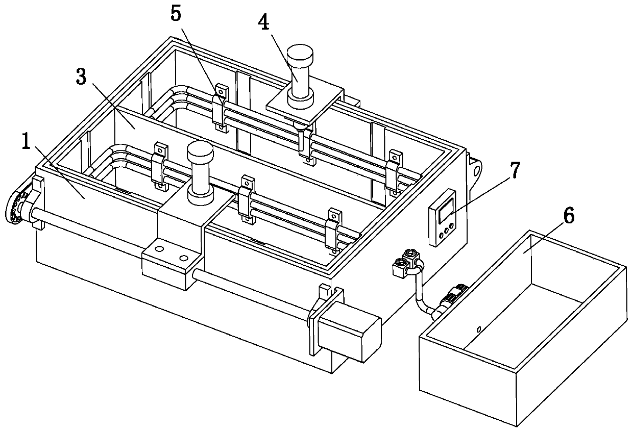
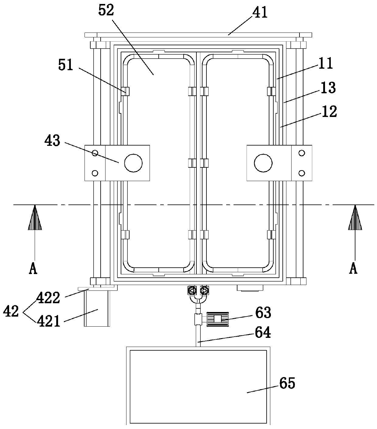
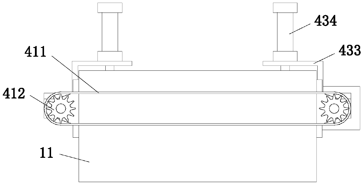
The invention relates to the field of chemical industrial equipment, and discloses an electrolytic cell temperature regulating and controlling device. The electrolytic cell temperature regulating andcontrolling device comprises a tank body, wherein a partition plate capable of separating the inner space of the tank body into two containing cavities is arranged in the tank body; the tank body comprises an inner-layer frame plate, a middle-layer frame plate and an outer-layer frame plate, wherein the inner-layer frame plate, the middle-layer frame plate and the outer-layer frame plate are mutually bonded and fixed, the outer side wall of the outer-layer frame plate is provided with a detection mechanism capable of detecting the temperature of the two containing cavities, a regulation and control mechanism is arranged in each containing cavity, a water supply mechanism is arranged beside the tank body, a controller is arranged on the outer side wall of the outer-layer frame plate, and the detection mechanism, the regulation and control mechanisms and the water supply mechanism are electrically connected with the controller. According to the electrolytic cell temperature regulating and controlling device, the temperature of the containing cavities can be automatically detected through the detection mechanism, the labor force is reduced, the detection efficiency is high, and the measurement period is short; and the regulation and control mechanism is matched with the water supply mechanism, so that the temperature regulation and control operation of the containing cavities canbe realized in real time.

Description

technical field [0001] The invention relates to the field of chemical industry equipment, in particular to an electrolytic tank temperature control device and a control method. Background technique [0002] In the production of aluminum electrolysis, the current efficiency is closely related to the temperature of the electrolyte. If the electrolyte temperature is too high, the secondary reaction of aluminum will be enhanced, the current efficiency will be reduced, and the consumption of materials will be increased. very high. Therefore, in order to obtain higher current efficiency, it is necessary to control the primary crystal temperature and superheat of the electrolyte, which requires real-time sensing of electrolyte temperature changes in the actual production operation process, so as to make timely adjustments to the production operation, so that aluminum Electrolysis production is running normally. [0003] At present, the existing electrolyte temperature measuremen...

Claims


Application Information

Patent Timeline
IPC IPC(8): C25C3/20
CPCC25C3/20
Inventor 陈雨
Owner 陈雨
Learn More