Discharging mechanism

A technology of blanking and receiving trays, used in punching machines, presses, and dust removal, etc., can solve problems such as low work efficiency, and achieve the effects of high work efficiency, ingenious design and simple structure.

Inactive Publication Date: 2019-10-18
俞斌
View PDF10 Cites 1 Cited by
  • Summary
  • Abstract
  • Description
  • Claims
  • Application Information

AI Technical Summary

Problems solved by technology

[0004] The problem to be solved by the present invention is to provide a blanking mechanism to overcome the defects of low work efficiency in the prior art

Method used


Image

  • Discharging mechanism
  • Discharging mechanism

Examples


Embodiment Construction

[0013] The specific implementation manners of the present invention will be further described in detail below in conjunction with the accompanying drawings and embodiments. The following examples are used to illustrate the present invention, but are not intended to limit the scope of the present invention.

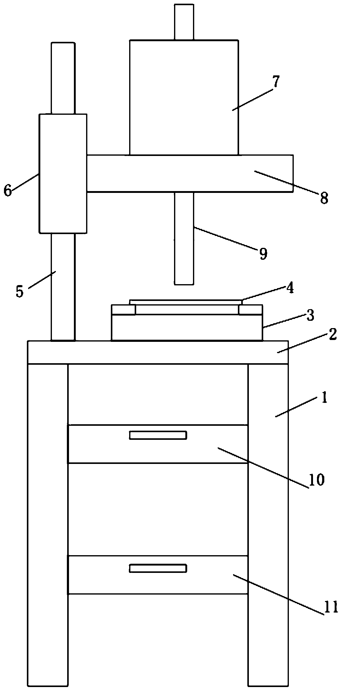
[0014] Such as figure 1 As shown, a blanking mechanism of the present invention includes a support 1, a workbench 2, a fixture 3, a product 4, a column 5, a shaft sleeve 6, an oil cylinder 7, an oil cylinder seat 8 and an oil cylinder piston rod 9; the support 1 There are four, the upper ends of the four brackets 1 are directly screwed and installed together with the workbench 2, and the lower ends are placed on the ground; the tooling fixture 3 is detachably arranged on the upper end of the workbench 2 by screws; The product 4 is directly placed on the upper end of the fixture 3; the column 5 is cylindrical, the upper end is directly slidingly connected with the shaft sl...


PUM


Abstract

The invention provides a discharging mechanism which comprises four brackets, a worktable, a tool clamp, a product, a column, a shaft sleeve, an oil cylinder, an oil cylinder seat and an oil cylinderpiston rod. The upper ends of the four brackets and the worktable are fixedly mounted together through screws and the lower ends of the brackets are placed on the ground; the tool clamp is detachablyarranged at the upper end of the worktable through screws; the product is directly placed at the upper end of the tool clamp; the column is cylindrical, and the upper end of the column is directly slidably connected to the shaft sleeve while the lower end of the column and the worktable are fixedly mounted together through screws. The discharging mechanism provided by the invention is simple in structure, skillful in design and high in punching working efficiency, and the height of the discharging mechanism up and down can be adjusted.

Description

technical field [0001] The invention relates to the technical field of blanking and stamping equipment, in particular to a blanking mechanism. Background technique [0002] Stamping is a forming processing method that applies external force to plates, strips, pipes and profiles by presses and molds to cause plastic deformation or separation to obtain workpieces (stamping parts) of required shape and size. Stamping and forging belong to plastic processing (or pressure processing) and are collectively called forging. The blanks for stamping are mainly hot-rolled and cold-rolled steel sheets and strips. Among the steel products in the world, 60-70% are plates, most of which are stamped into finished products. The body, chassis, fuel tank, radiator fins of the car, the steam drum of the boiler, the shell of the container, the iron core silicon steel sheet of the motor and electrical appliances, etc. are all stamped. There are also a large number of stamping parts in products ...

Claims


Application Information

Patent Timeline
Patent Type & Authority Applications(China)
IPC IPC(8): B21D28/24B21D43/00B08B15/04B30B1/32
CPCB08B15/04B21D28/24B21D43/003B30B1/32
Inventor 俞斌
Owner 俞斌
Why Eureka
Try Eureka