
Low attenuation gradient orbital angular momentum fiber

An orbital angular momentum and graded technology, which is applied in the direction of graded index core/cladding fiber, cladding fiber, multi-layer core/cladding fiber, etc., can solve the problem of fiber structure viscosity matching imbalance, crosstalk and fiber Attenuation increase, fiber virtual temperature increase and other problems, to achieve the effect of optimizing fiber design, reducing attenuation coefficient, and reducing defects

Active Publication Date: 2019-10-15
YANGTZE OPTICAL FIBRE & CABLE CO LTD
View PDF16 Cites 8 Cited by
  • Summary
  • Abstract
  • Description
  • Claims
  • Application Information

AI Technical Summary

Problems solved by technology

In this way, the actual drawing and laying of defects in the core-cladding interface will have a more obvious impact on the coupling between modes, resulting in increased crosstalk and fiber attenuation
Chinese patent CN108680990A reports a ring-core orbital angular momentum optical fiber, but its attenuation is greater than 1dB / km, so it can only be used for short-distance transmission
Chinese patent CN106338793A reports that an RCF fiber can suppress some high-order modes that are easy to couple, but its attenuation is 0.31dB / km, which still has a certain gap with low-loss FMF
In this way, the viscosity of the core layer of the pure silicon core is relatively high, and at the same time, the viscosity of the inner cladding layer doped with a large amount of F is relatively low, which will cause an imbalance in the viscosity matching of the fiber structure, so that the virtual temperature of the fiber will increase rapidly, resulting in the R of the fiber. d Increase
This not only offsets the benefits brought by the reduction of doping, but also may cause the fiber attenuation reverse anomaly

Method used


Image

  • Low attenuation gradient orbital angular momentum fiber
  • Low attenuation gradient orbital angular momentum fiber
  • Low attenuation gradient orbital angular momentum fiber

Examples


Embodiment Construction

[0043] The present invention will be further described in detail below in conjunction with the accompanying drawings and embodiments.

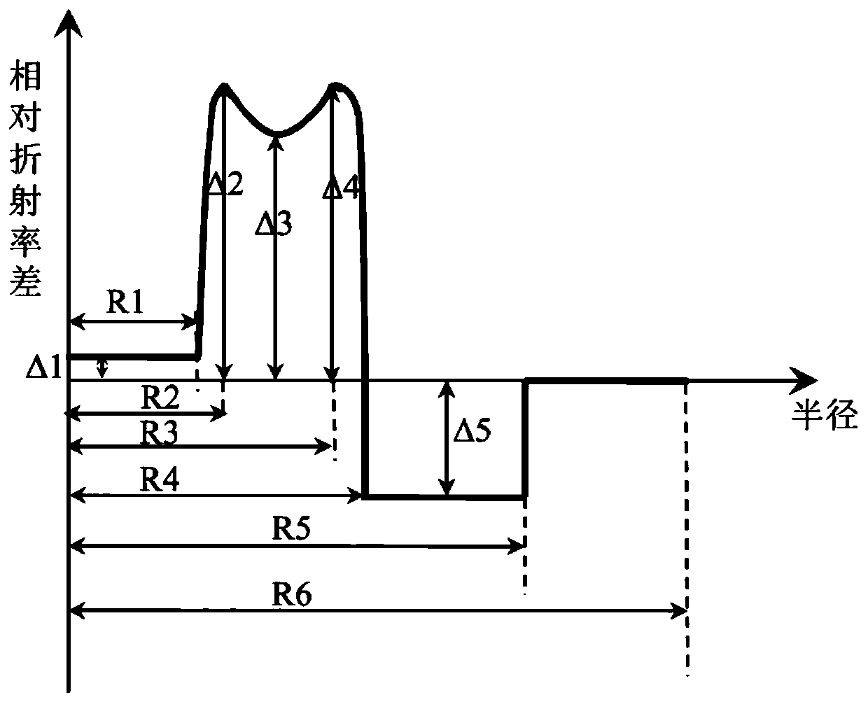
[0044] It includes a core layer and a cladding layer. The radius of the core layer is R1, and the relative refractive index difference of the core layer is Δ1. The layer is gradually deformed, and the top is gradually concave. The annular core layer is divided into three parts: the inner ring layer, the lower concave layer and the outer ring layer from the inside to the outside. The radius of the inner ring layer is R2, and the maximum relative refraction The rate difference is Δ2, the radius of the depressed layer is R3, the minimum relative refractive index difference is Δ3, the radius of the outer ring layer is R4, the maximum relative refractive index difference is Δ4, and the radius of the depressed cladding is R5, the relative refractive index difference is Δ5, the above-mentioned relative refractive index difference is the relative refr...


PUM


Abstract

The invention relates to a low attenuation gradient orbital angular momentum fiber. The low attenuation gradient orbital angular momentum fiber includes a core layer and a cladding layer; the core layer radius R1 is 3.5 [Mu]m to 5.5 [Mu]m, and the [Delta]1 is -0.08% to 0.08%; the core layer is covered by a ring core layer, a depressed cladding layer and an outer cladding layer; the ring core layerhas a gradual shape, and the top portion has a gradual concave shape, and is successively divided into an inner ring layer, a lower concave layer and an outer ring layer from the inside to the outside; the inner ring layer has a radius R2 of 4.5 [Mu]m to 6.5 [Mu]m and a [Delta]2 of 0.7% to 1%; the lower concave layer radius R3 is 8 [Mu]m to 13 [Mu]m, and the [Delta]3 is 0.6% to 0.9%; the outer ring layer has a radius R4 of 9[Mu]m to 15[Mu]m and a [Delta]4 of 0.7% to 1%; and the depressed cladding layer radius R5 is 11 [Mu]m to 16 [Mu]m, and the [Delta]5 is 0.6% to 0.3%; the relative refractive index difference is the relative refractive index difference between each layer of the fiber and the outer cladding layer; and the outer cladding layer is an outer cladding layer with a negative refractive index relative to a pure silicon dioxide layer. The low attenuation gradient orbital angular momentum fiber not only can support long-distance signal transmission with low attenuation of fourmode groups, but also has good comprehensive performances in crosstalk of the optical fiber, macro-bend and micro-bend loss of each mode and the like.

Description

technical field [0001] The invention relates to a space-division multiplexing transmission optical fiber used in an optical fiber communication system, in particular to a low-attenuation gradual orbital angular momentum (OAM) optical fiber. Background technique [0002] In recent years, with the rise of cloud computing, big data, and mobile Internet, data centers with efficient inter-server collaboration and data processing capabilities have become an obvious hotspot for the growth of information volume and information density, thus affecting the interconnection communication rate of data centers. urgent demands for improvement. Due to the characteristics of large number of devices, complex wiring, and high interface density in data center interconnection communication, relying only on improving device modulation bandwidth, increasing the number of optical fiber links or output light sources with different stable wavelengths will inevitably increase the cost of system operat...

Claims


Application Information

Patent Timeline
Patent Type & Authority Applications(China)
IPC IPC(8): G02B6/028G02B6/036
CPCG02B6/0283G02B6/03611G02B6/03694
Inventor 沈磊张磊张睿吴俊刘亚萍周红燕曹蓓蓓
Owner YANGTZE OPTICAL FIBRE & CABLE CO LTD
Learn More