All-dielectric filter

A filter and all-dielectric technology, applied in the field of all-dielectric filters, can solve problems such as difficult and unfavorable large-area preparation, and achieve the effect of reducing transmittance and high-efficiency filtering performance

Inactive Publication Date: 2019-10-15
SUZHOU UNIV
View PDF6 Cites 0 Cited by
  • Summary
  • Abstract
  • Description
  • Claims
  • Application Information

AI Technical Summary

Problems solved by technology

However, the height of this multilayer structure is as high as 3 μm, while the width of each nanorod is only 0.26 μm. The etching with such a high aspect ratio (height / width) brings great difficulties to the experimental preparation, which is not conducive to large area preparation

Method used


Image

  • All-dielectric filter
  • All-dielectric filter
  • All-dielectric filter

Examples


Embodiment Construction

[0031] In order to make the purpose, technical solutions and advantages of the embodiments of the present invention more clear, the following will clearly and completely describe the technical solutions of the embodiments of the present invention in conjunction with the drawings of the embodiments of the present invention. Apparently, the described embodiments are some, not all, embodiments of the present invention. All other embodiments obtained by those skilled in the art based on the described embodiments of the present invention belong to the protection scope of the present invention.

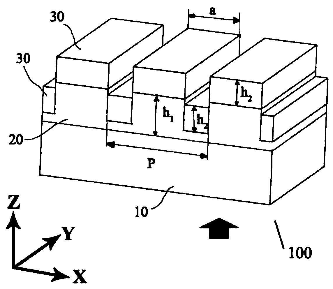
[0032] In the description of the present invention, it should be understood that the orientation or positional relationship indicated by the terms "upper", "lower", etc. is based on the attached figure 1 The orientations or positional relationships shown are only for the convenience of describing the present invention and simplifying the description, but do not indicate or imply that the re...


PUM


Abstract

The invention discloses an all-dielectric filter. The all-dielectric filter comprises a substrate, a first dielectric layer and a second dielectric layer, wherein the first dielectric layer is provided with a wire grid structure; the first dielectric layer is arranged on the substrate; the second dielectric layer is arranged on the first dielectric layer; and the refractive index of the second dielectric layer is higher than that of the first dielectric layer. According to the filter disclosed by an embodiment of the invention, the first dielectric layer and the second dielectric layer with the high refractive index and the low refractive index are used, so that the transmittance is greatly reduced under the incidence of TM light waves, and only normally incident light can pass through anangle filter. An experimental result shows efficient filtering performance. The filter disclosed by the embodiment of the invention has an important application prospect in directional illumination and image shaping.

Description

technical field [0001] The invention relates to an optical device, in particular to an all-dielectric filter. Background technique [0002] At present, almost all angle filters are designed and manufactured based on Zero Index Material. The principle is that at the interface of two different materials, the wave vector must be continuous. When one of the materials has a refractive index of zero, the wavevector length of the beam propagating inside it is also zero. In this way, at the interface of these two materials, the wave vector length in the other material must also be 0 to satisfy the wave vector matching condition. At this time, if the refractive index of the material is not 0, then only the light wave vector whose propagation direction is perpendicular to the interface is 0, so that only the light emitted vertically can pass through, and angle filtering is realized. Due to the refractive index of the material (where ε is the permittivity, μ is the magnetic permea...

Claims


Application Information

Patent Timeline
IPC IPC(8): G02B5/20
CPCG02B5/204
Inventor 钱沁宇王钦华
Owner SUZHOU UNIV
Why Eureka
Try Eureka