
Chip component slitting, molding detection and braiding linkage integrated machine

An all-in-one machine and component technology, which is applied in the field of chip component processing equipment, can solve the problems of low processing efficiency, high processing cost, and many manual participation parts, and achieves the effect of fast component taping, compact structure, and cost saving of taping.

Active Publication Date: 2019-10-15
广东南方宏明电子科技股份有限公司
View PDF8 Cites 7 Cited by
  • Summary
  • Abstract
  • Description
  • Claims
  • Application Information

AI Technical Summary

Problems solved by technology

[0002] With the development of science and technology and the improvement of the level of electronic technology, as well as the miniaturization of electronic products, the further improvement of performance and reliability, electronic components have developed from large, heavy, and thick to small, light, and thin. Capacitors, thermistors, varistors and other chip components, chip components need to go through chip welding, plastic sealing, slitting, lead forming, taping and other processes in the production process, traditional chip component production requires different equipment It is carried out step by step, there are many manual parts involved, the processing cost is high, the processing efficiency is low, and it is easy to produce waste components

Method used


Image

  • Chip component slitting, molding detection and braiding linkage integrated machine
  • Chip component slitting, molding detection and braiding linkage integrated machine
  • Chip component slitting, molding detection and braiding linkage integrated machine

Examples


Embodiment

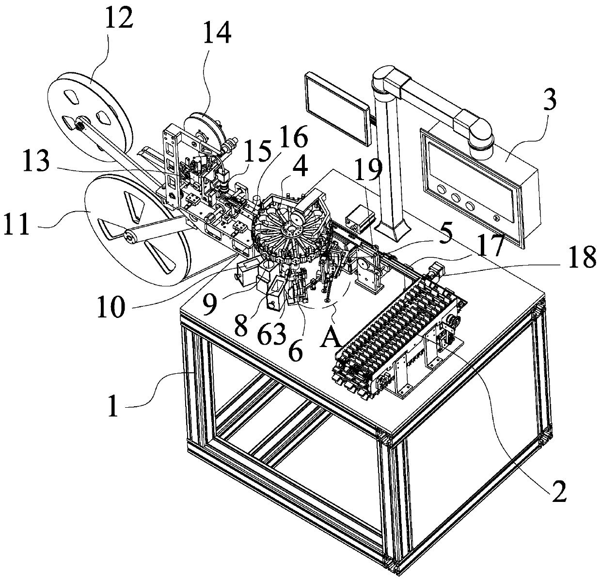
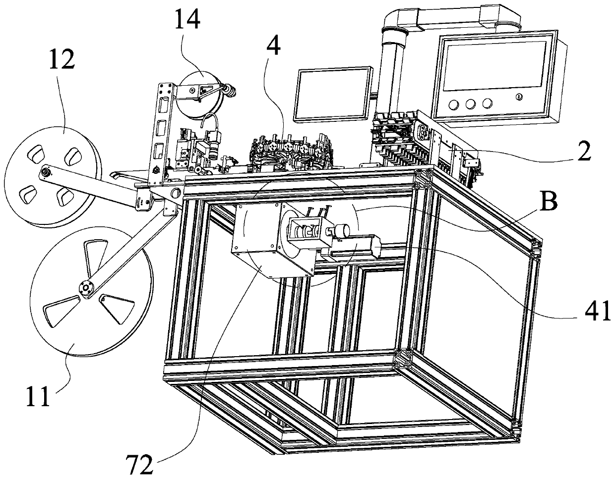
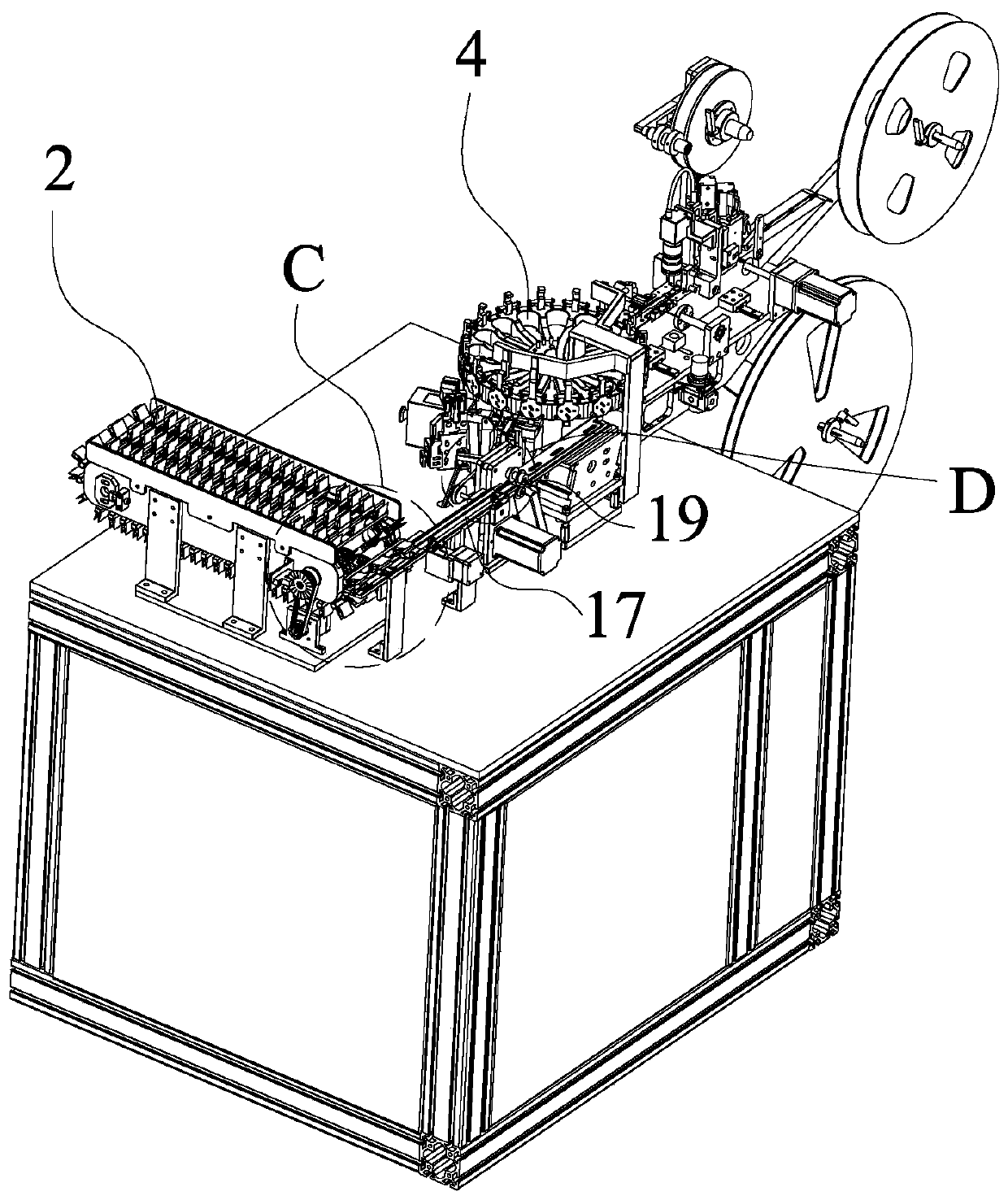
[0027] Example: such as Figure 1-7As shown, the present invention is an integrated machine for slitting, forming, detecting, and braiding of chip components, including a frame 1, a feeding mechanism 2, a control panel 3, a turntable mechanism 4, a first lead wire bending mechanism 5, and a second lead wire Bending mechanism 6, forming driving mechanism 7 and feeding channel 17, the feeding channel 17 is installed on the frame 1, and the feeding mechanism 2, pinch feeding mechanism 18, cutting mechanism 19 and turntable mechanism are arranged in sequence along the feeding channel 17 4. The periphery of the turntable mechanism 4 is sequentially provided with a first lead wire bending mechanism 5, a second lead wire bending mechanism 6, an electric measuring mechanism 63, a first defective product discharge groove 8, a CCD shape detection mechanism 9, and a second non-conductive wire bending mechanism. A good product discharge trough 10 and a blanking and braiding mechanism, a f...


PUM


Abstract

The invention discloses a chip component slitting, molding detection and braiding linkage integrated machine. The chip component slitting, molding detection and braiding linkage integrated machine comprises a rack. A feeding channel is mounted on the rack. A feeding mechanism, a clamping and conveying mechanism, a slitting mechanism and a rotary disk mechanism are arranged on the feeding channel in sequence. A first wire bending mechanism, a second wire bending mechanism, an electric detection mechanism, a first defective product discharge tank, a CCD contour detection mechanism, a second defective product discharge tank and a discharging and braiding mechanism are arranged on the periphery of the rotary disk mechanism in sequence. A molding driving mechanism is mounted on the lower side of the rack. The molding driving mechanism drives the first wire bending mechanism and the second wire bending mechanism. The first wire bending mechanism and the second wire bending mechanism are matched with the rotary disk mechanism to operate. The discharging and braiding mechanism comprises a braiding channel. A braid charging position, a CCD braid charging detection mechanism, a braid covering mechanism and a braid carrying reel are arranged along the braiding channel in sequence. The chip component slitting, molding detection and braiding linkage integrated machine realizes slitting, molding detection and packaging full-automatic of chip components, improves the braiding efficiency and saves the braiding cost.

Description

technical field [0001] The invention relates to an integrated machine for slitting, forming, and testing, in particular to an integrated machine for slitting, forming, testing, and braiding of chip components, which belongs to the technical field of chip component processing equipment. Background technique [0002] With the development of science and technology and the improvement of electronic technology level, as well as the miniaturization of electronic products, the further improvement of performance and reliability, electronic components have developed from large, heavy and thick to small, light and thin. Capacitors, thermistors, varistors and other chip components, chip components need to go through chip welding, plastic sealing, slitting, lead forming, taping and other processes in the production process, traditional chip component production requires different equipment It is carried out step by step, and there are many manual parts involved, the processing cost is h...

Claims


Application Information

Patent Timeline
Patent Type & Authority Applications(China)
IPC IPC(8): B26D1/24B26D7/06B07C5/34B07C5/344B07C5/36B07C5/38B21F1/00B65B15/04B29C63/02
CPCB07C5/34B07C5/344B07C5/362B07C5/38B21F1/00B26D1/24B26D7/06B26D7/0658B29C63/02B65B15/04
Inventor 罗世勇赵俊斌梁伟鸿罗致成
Owner 广东南方宏明电子科技股份有限公司
Learn More