
Memory system and electronic device

A technology for memory systems and electronic devices, applied in memory systems, protection of stored content to prevent loss, instruments, etc., can solve the problems of increasing the number of writes to non-volatile memory, shortening the life of non-volatile memory, etc., so as to extend the life. , the effect of prolonging the processing time and reducing the number of writes

Pending Publication Date: 2019-10-11
KYOCERA DOCUMENT SOLUTIONS INC
View PDF13 Cites 0 Cited by
  • Summary
  • Abstract
  • Description
  • Claims
  • Application Information

AI Technical Summary

Problems solved by technology

Therefore, if the power supply of the image forming apparatus is frequently switched on / off, the number of times of writing to the nonvolatile memory increases, and the life of the nonvolatile memory is shortened.

Method used


Image

  • Memory system and electronic device
  • Memory system and electronic device
  • Memory system and electronic device

Examples


Embodiment Construction

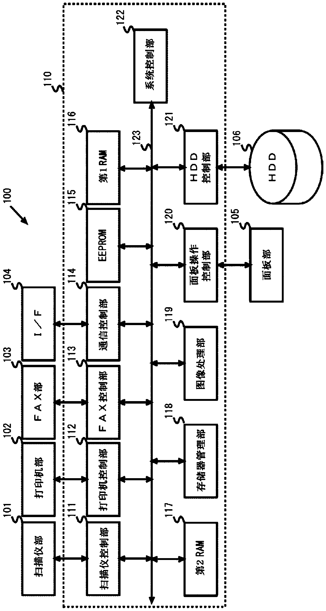
[0026] Below, refer to Figure 1 ~ Figure 3 One embodiment of the electronic device of the present invention will be described. In addition, as an example of the electronic device in the following description, it is assumed that, for example, it is a composite peripheral device equipped with a printing function, a copying function, a FAX function, and a data transmission and reception function via a network, that is, an MFP (Multifunction Peripheral, multifunction digital device). all-in-one machine).

[0027] First, if figure 1 As shown, MFP 100 includes control unit 110 for controlling operations of scanner unit 101 , printer unit 102 , FAX unit 103 , I / F (interface) 104 , panel unit 105 , and HDD (Hard Disk Drive) 106 . In addition, MFP 100 in this embodiment assumes that HDD 106 is mounted, but HDD 106 may not be mounted.

[0028] The scanner unit 101 is a device that converts an image on a paper (not shown) read by an image sensor (not shown) into digital image data, a...


PUM


Abstract

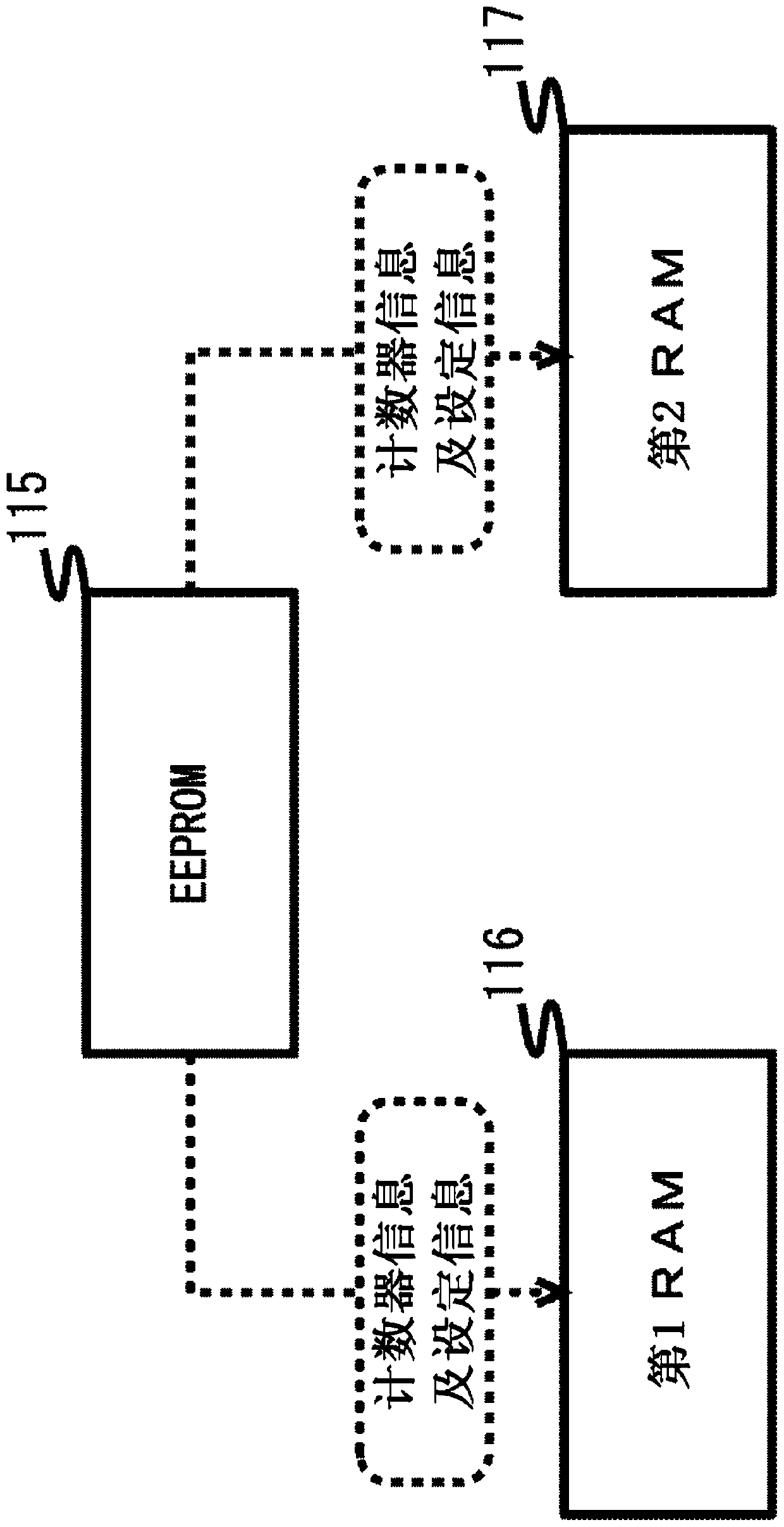
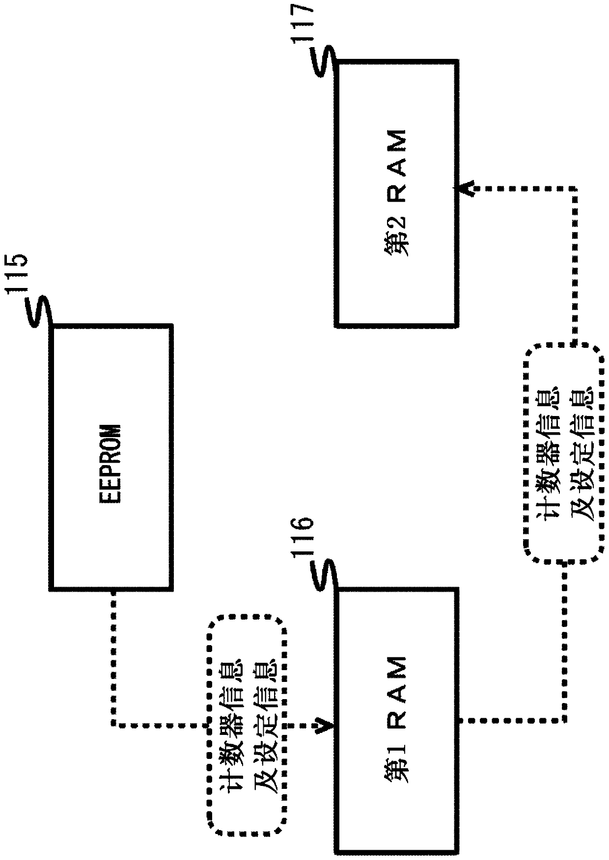
The purpose of the present invention is to avoid prolonging processing time involved in a power supply being switched on and off and to extend the useful lifespan of non-volatile memory. Counter information and setting information are stored by an EEPROM (115). The counter information and setting information are stored by a first RAM (116) and a second RAM (117). Storage regions for the counter information and setting information in the first RAM (116) are managed as updatable, and storage regions for the counter information and the setting information of the second RAM (117) are managed as non-updatable, by a memory management unit (118). When a change occurs in the content of the counter information and setting information, the counter information and setting information of the first RAM(116) are overwritten by a system control unit (122) according to the content of the change. When the power supply is switched off, the counter information and setting information of the first RAM (116) and the counter information and setting information of the second RAM (117) are read and compared, and only the information differing therebetween is written to the EEPROM (115).

Description

technical field [0001] The present invention relates to memory systems and electronic devices suitable for the use of non-volatile memories. Background technique [0002] For example, various consumable parts are mounted on an image forming apparatus such as an MFP (Multifunction Peripheral), which is one of electronic devices. As consumable parts, when a printing function, a copying function, a FAX function, a data transmission and reception function via a network, and the like are mounted, unit parts that execute each function belong to this. In addition, a rewritable nonvolatile memory, a volatile memory used as a work memory for executing a program, and the like also belong to the consumable parts. In addition, the nonvolatile memory stores counter information for determining the replacement timing of each unit component, setting information related to each function, and the like. [0003] However, in the image forming apparatus, when the power is turned on, the above-...

Claims


Application Information

Patent Timeline
Patent Type & Authority Applications(China)
IPC IPC(8): G06F12/16
CPCG06F12/0246G06F2212/7203G06F2212/7206G06F2212/1032G06F12/0868G06F3/0611G06F3/0616G06F3/0659G06F3/0685
Inventor 岩崎幸雄
Owner KYOCERA DOCUMENT SOLUTIONS INC
Learn More