A resistor that utilizes an integral ceramic tube to isolate resistance elements
A technology for isolating resistors and resistors, applied in the direction of resistors, electrical components, resistor parts, etc., can solve the problems of shortening the creepage distance, failing to meet the high pressure requirements of the rainy environment, and affecting the insulation performance of the resistance unit, etc., to achieve simplification The way of isolation, the improvement of the overall insulation performance, and the effect of meeting the requirements of high voltage resistance
- Summary
- Abstract
- Description
- Claims
- Application Information
AI Technical Summary
Problems solved by technology
Method used
Image
Examples
Embodiment 1
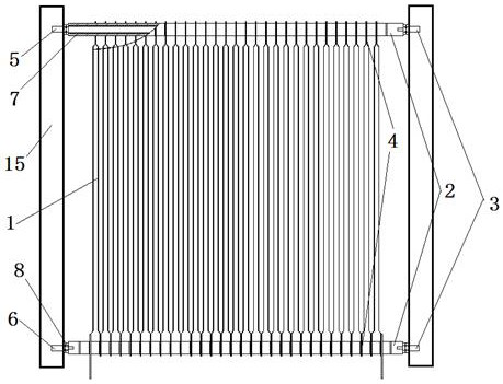
[0038] by attaching Figure 2-7 It can be seen that the present invention relates to a resistor that utilizes an integral porcelain tube to isolate resistance elements, including a frame, and a resistance unit is installed in the frame, and the resistance unit is fastened to the frame through a support member; the resistance unit is a resistor The chip resistance unit is formed by rounding up and down the strip or the resistance piece; the resistance unit includes the support rod 3, the resistance strip 1 and the whole insulation tube 2, and is formed by combining the support pole 3, the resistance strip 1 and the whole insulation tube 2 The resistance unit, the isolation and positioning of the upper and lower ends 4 of the resistance band 1 are isolated and positioned through the whole insulating tube.
[0039] The support rod 3 is a cylindrical metal rod commonly called a tie rod, and there are two support rods 3, which are respectively the first support rod 5 and the second...
Embodiment 2
[0046] The principle of embodiment two is the same as embodiment one, but the structure is slightly different, and the different parts are as attached Figure 8-10 As shown, a resistor that utilizes an integral ceramic tube to isolate resistance elements includes a frame, and a resistance unit is installed in the frame, and the resistance unit is fastened to the frame through a support member; the resistance unit is a resistance band or a resistance sheet The chip resistance unit is formed by winding up and down. The resistance unit includes a support rod 203, a resistance band 201, a whole insulating tube 202 and a conductor 213. The resistance unit is formed by combining the support bar 203, the resistance band 201 and the whole insulating tube 202; During the isolation and positioning of the two ends of the resistance band 202, the isolation and positioning are carried out through the entire insulating tube 202 (as attached Figure 8 shown).
[0047] The support rod 203 is...
Embodiment 3
[0054] The principle of the third embodiment is the same as that of the second embodiment, except that the structure of the insulating tube is slightly different, and the different parts are as attached Figure 11 and 12 As shown, a resistor that utilizes an integral ceramic tube to isolate resistance elements includes a frame, and a resistance unit is installed in the frame, and the resistance unit is fastened to the frame through a support member; the resistance unit is a resistance band or a resistance sheet The chip resistance unit is composed of up and down circuitous molding. The resistance unit includes a support rod 303, a resistance band 301, and an integral porcelain tube 302. The resistance unit is formed by combining the support bar 303, the resistance band 301 and the overall porcelain tube 302. Its characteristic is that the resistance band The isolation and positioning of the two ends are carried out through the whole ceramic tube.
[0055] It’s just that the i...
PUM
 Abstract
Description
Claims
Application Information
 - Generate Ideas
- Intellectual Property
- Life Sciences
- Materials
- Tech Scout
- Unparalleled Data Quality
- Higher Quality Content
- 60% Fewer Hallucinations
Browse by: Latest US Patents, China's latest patents, Technical Efficacy Thesaurus, Application Domain, Technology Topic, Popular Technical Reports.
© 2025 PatSnap. All rights reserved.Legal|Privacy policy|Modern Slavery Act Transparency Statement|Sitemap|About US| Contact US: help@patsnap.com


