
Structural and functional integrated tempered vacuum glass and manufacturing method thereof

A technology of vacuum glass and manufacturing method, which is applied in the field of building materials production, can solve the problems of low safety performance of vacuum glass, loss of tempering performance, and reduced performance of tempered glass, etc., and achieves excellent safety and reliability, broad application market, and enhancement of peripheral strength.

Active Publication Date: 2019-10-11
许浒
View PDF12 Cites 0 Cited by
  • Summary
  • Abstract
  • Description
  • Claims
  • Application Information

AI Technical Summary

Problems solved by technology

[0004] The purpose of the present invention is to solve the existing vacuum glass, which will seriously reduce the performance of tempered glass during the production process, or even lose the toughening performance, especially the peripheral strength of tempered flat glass will be greatly reduced, it is difficult to make multi-vacuum layer vacuum glass, and the current There is a vacuum glass with low safety performance and unsatisfactory thermal insulation performance, but the production method of the structural and functional integrated tempered vacuum glass and the structural and functional integrated tempered vacuum glass produced by the production method are provided.

Method used


Image

  • Structural and functional integrated tempered vacuum glass and manufacturing method thereof
  • Structural and functional integrated tempered vacuum glass and manufacturing method thereof
  • Structural and functional integrated tempered vacuum glass and manufacturing method thereof

Examples


Embodiment 1

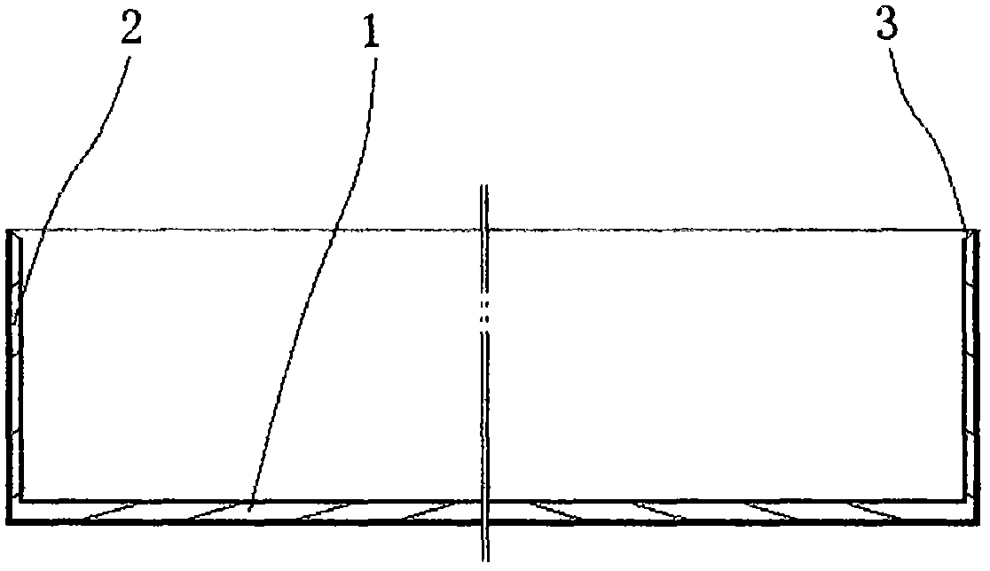
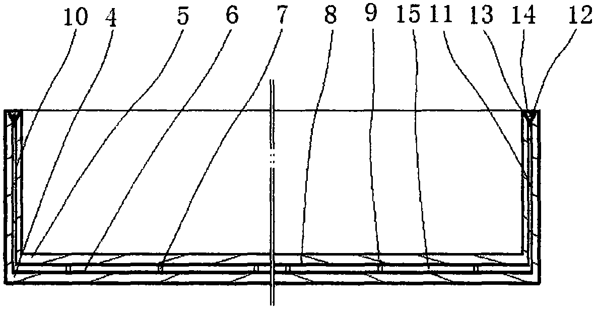
[0049] Embodiment one: according to Figure 1 , Figure II Shown to make:

[0050] (1) Make and shape the face wall toughened hem glass 4 and the inner wall toughened hem glass 5 of the single-sided opening made of the face wall 1, the hem 2 and the hem sealing surface 3 respectively, the length of the inner wall toughened hem glass 5 , The outer width dimension is smaller than the length and width inner dimension of the wall-folding glass 4 by 0.05mm-5mm.

[0051] (2) Place the tempered glass 4 facing the wall with the opening facing upwards, and place the pin 7 at the corresponding position on the inner surface 6 of the facing wall.

[0052] (3) Place the outer surface 8 of the inner wall tempered hemming glass 5 on the upper surface 9 of the pin, and make the inner wall tempered hemming glass hemming outer surface 10 meet with the face wall tempered hemming glass hemming inner surface 11 or leave a 0.05 mm-5mm clearance.

[0053] (4) Place the melting temperature at 300...

Embodiment 2

[0055] Embodiment two: according to Figure three Shown to make:

[0056] (1) Place the tempered glass 4 facing the wall with the opening facing up in water, tin or powder 16, and make the surface of water, tin or powder 16 inside and outside the workpiece higher than the outer surface of the tempered glass 5 on the inner wall by 3mm- 30mm. Then, the sealing heating device is turned on again, and the sealing low-temperature sealing material 14 is heated locally at 300°C-450°C in a manner of gradually increasing the temperature, so that the sealing low-temperature sealing material 14 melts and realizes the hemming with the inner wall tempered hemming glass of sealing.

[0057] (2) Take out the sealed workpiece from water, tin or powder 16, vacuumize the vacuum layer 15 through the vacuum hole 17, and turn on the vacuum after the vacuum degree of the vacuum layer 15 reaches the set vacuum degree The hole sealing device is used to locally heat the vacuum hole 17 to melt the lo...

Embodiment 3

[0058] Embodiment three: according to Figure four The schematic diagram of the product structure shown:

[0059] (1) After placing the column pin 7 at the corresponding position on the inner surface 6 of the wall, place a pre-formed separation layer 19 on the upper surface of the column pin 7, the separation layer hem 20 is in contact with the inner surface 11 of the tempered glass hem hem of the wall or Leave a gap of 0.05mm-5mm.

[0060] (2) Place the second-layer pins 7-1 on the corresponding positions on the upper surface of the separation layer 19, and align the second-layer pins 7-1 with the pins 7 up and down, and repeat this to form a multi-vacuum layer structure.

[0061] (3) Place the outer surface 8 of the inner tempered hemmed glass 5 on the upper surface of the upper pin, and make the inner wall tempered hemmed glass hemmed outer surface 10 meet the separation layer hem 20 or leave a gap of 0.05mm-5mm .

[0062] (4) Place the melting temperature at 300°C-450°C...


PUM


Abstract

The invention discloses structural and functional integrated tempered vacuum glass and a manufacturing method thereof. The vacuum glass has remarkable advantages that the vacuum glass forms a stereoscopic stress structure by folded edges, bending resistance and breaking strength are remarkably enhanced, the peripheral strength of the vacuum glass is remarkably enhanced, and excellent heat insulation performance, safety and reliability are given to the vacuum glass by the aid of unique folded edges, a plurality of vacuum layers and a high-thickness vacuum layer structure and the manufacturing method. The vacuum glass solves the problem that industrial development of the glass is seriously restricted as safety of existing vacuum glass is low, and the vacuum glass has vital significance for development of projects, products and industries. The durability of the vacuum glass is ten times or more of that of the existing vacuum glass, so that the service life of the vacuum glass is as same as that of a building. The vacuum glass serving as a structural and functional integrated product is wide in application market. The heights and the thicknesses of the folded edges and the thicknesses,the layer number and the vacuum degree of the vacuum layers are adjusted, and bending resistance, fracture resistance, impact strength and heat insulation properties are correspondingly set, so thatthe vacuum glass serving as a structural and functional integrated material completely meets the requirement that energy consumption of the building is reduced by 65%-75%, and the vacuum glass also meets comprehensive requirements such as passiveness and zero energy consumption of the building for curtain walls, walls, roofs, doors and windows.

Description

technical field [0001] The invention belongs to the technical field of building material production, and in particular relates to a method for manufacturing structural-function-integrated tempered vacuum glass and the structural-function-integrated tempered vacuum glass produced by the method. Background technique [0002] The current manufacturing process of vacuum glass is to place supports on the tempered flat glass, then spread solder on the edge between two parallel tempered flat glasses, then weld and seal at high temperature, and finally pump air to form a vacuum. Existence: 1. When the solder is melted at high temperature at the edge of two parallel tempered flat glasses, because the heating part is on the same plane as the inner and outer vacuum walls of the vacuum glass, the heat transfer distance cannot be extended, and it is difficult to significantly reduce the high temperature of the heating part on the inner and outer vacuum walls. 2. The peripheral strength o...

Claims


Application Information

Patent Timeline
IPC IPC(8): C03C27/10
CPCC03C27/10
Inventor 许浒许敬修
Owner 许浒
Learn More