Calibration device and radar and camera combined calibration method and system

A calibration device and joint calibration technology, applied in the field of calibration, can solve the problems of ignoring angle deviation, etc., and achieve the effects of simple device, accurate calibration effect and simple method

Active Publication Date: 2019-10-08
XIAMEN KING LONG UNITED AUTOMOTIVE IND CO LTD
View PDF8 Cites 12 Cited by
  • Summary
  • Abstract
  • Description
  • Claims
  • Application Information

AI Technical Summary

Problems solved by technology

At present, there are few related studies on the joint calibration of binocular cameras and millimeter-wave radars at home and abroad. In the existing technology, the external parameters between the millimeter-wave radar and the camera are usually obtained by directly measuring the displacement deviation, and the angle deviation is generally ignored.

Method used


Image

  • Calibration device and radar and camera combined calibration method and system
  • Calibration device and radar and camera combined calibration method and system
  • Calibration device and radar and camera combined calibration method and system

Examples


Embodiment 1

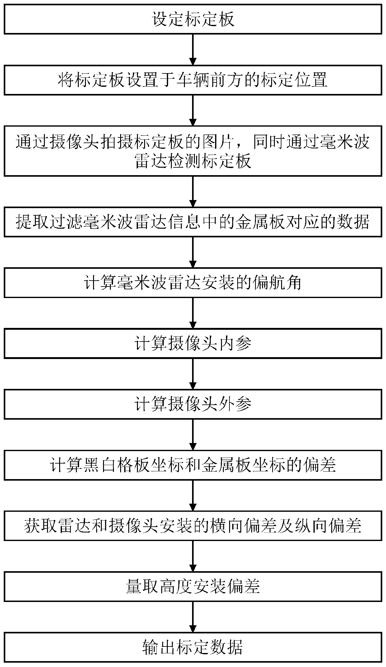
[0042] refer to figure 1 As shown, the present invention provides a radar and camera joint calibration method, comprising the following steps:

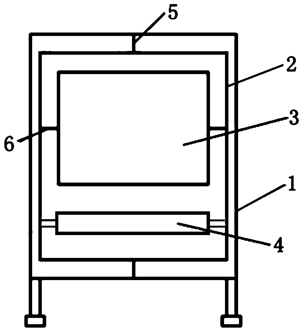
[0043] Step 1: Set up the calibration device.

[0044] The calibration device includes a bracket 1, an inner frame 2 mounted on the bracket 1 and capable of rotating around the vertical direction, a metal plate 4 fixedly mounted on the inner frame 2, and a metal plate 4 that rotates in a direction perpendicular to the direction of rotation of the inner frame 2. black and white grid board 3.

[0045] Since millimeter-wave radar has different reflectivity to metal and non-metal, in order to better extract the data of the metal plate 4 area from the collected radar data, therefore, in this embodiment, the metal plate 4 and the metal plate 4 are The other parts of the calibration device are made of different materials, that is, the metal plate 4 is made of metal, and other parts of the calibration device except the metal plate 4 are mad...

Embodiment 2

[0101] The present invention also provides a radar and camera joint calibration system, including the calibration device, camera, radar, and processing terminal as described in Embodiment 1, the processing terminal includes a memory, a processor and a bus, and the memory stores at least A program, the system implements the radar and camera joint calibration method as described in Embodiment 1 of the present invention.

[0102] The processor includes one or more processing cores, the processor is connected to the memory through the bus, the memory is used to store program instructions, and the processor implements the joint calibration of the radar and the camera described in Embodiment 1 of the present invention when executing the program instructions in the memory method.

[0103] Further, as an executable solution, the so-called processor can be a central processing unit (Central Processing Unit, CPU), and can also be other general-purpose processors, digital signal processo...


PUM


Abstract

The invention relates to a calibration device and a radar and camera combined calibration method and system, and the method comprises the steps: S1, providing a calibration device which comprises a camera calibration plate and a radar calibration plate, and enabling the calibration device to be located at a calibration position; S2, collecting pictures of the calibration device in different statesthrough a camera; meanwhile, through the radar detection calibration device, locating the camera calibration plate and the radar calibration plate in the same plane and jointly rotate by different angles around the first rotating shaft and rotate by different angles around the second rotating shaft; and S3, calculating calibration data according to the radar detection data corresponding to the time when the camera collects the picture, and outputting the calibration data, with the calibration data comprising a yaw angle, a pitch angle and a translation vector between the radar and the camera.According to the invention, the deviation of the installation angle is considered, so that the unification of the information obtained by the radar and the camera can be ensured and more accurate obstacle identification and tracking can be realized.

Description

technical field [0001] The present invention relates to the technical field of calibration, in particular to a calibration device, a radar and camera joint calibration method and system. Background technique [0002] Sensor fusion is a trend in the development of automobile safety. The combined use of cameras and radars can synthesize the characteristics of visual sensors and ranging sensors, learn from each other, and improve the overall perception and safety performance of automobiles. Specifically, for example, vehicle forward collision warning. [0003] In the multi-sensor perception system, to realize the information fusion of each sensor, a unified coordinate system is required, and the joint calibration of the external parameters of the camera and the millimeter-wave radar directly affects the accuracy of vehicle obstacle detection. At present, there are few related studies on the joint calibration of binocular cameras and millimeter-wave radars at home and abroad. I...

Claims


Application Information

Patent Timeline
Patent Type & Authority Applications(China)
IPC IPC(8): G06T7/80G01S7/40
CPCG01S7/40G06T7/80
Inventor 蔡樱贤李理欧敏辉柯志达陈卫强苏亮
Owner XIAMEN KING LONG UNITED AUTOMOTIVE IND CO LTD
Why Eureka
Try Eureka