Gas eddy preventing combustion device

A combustion device and gas vortex technology, which are applied to gas fuel burners, burners, combustion methods, etc., can solve problems such as flame instability, and achieve the effects of stable and uniform production, convenient processing and low cost.

Pending Publication Date: 2019-10-08
河南神玖天航新材料股份有限公司
View PDF11 Cites 0 Cited by
  • Summary
  • Abstract
  • Description
  • Claims
  • Application Information

AI Technical Summary

Problems solved by technology

[0003] The invention proposes an anti-gas vortex combustion device to solve the technical problem that the gas in the inner cavity of the existing combustion device forms a vortex and turbulent flow, which causes the flame ejected from the flame port to be unstable

Method used


Image

  • Gas eddy preventing combustion device
  • Gas eddy preventing combustion device
  • Gas eddy preventing combustion device

Examples


Embodiment 1

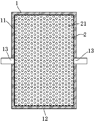
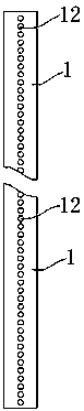
[0024] Embodiment 1 of the anti-gas vortex combustion device: the anti-gas vortex combustion device of this embodiment is mainly used for heating during the process of melting quartz raw materials to draw quartz fibers, including a combustion device housing 1, the combustion device housing of this embodiment 1. It is rectangular and strip-shaped, and 100 combustion holes are distributed on the periphery of the rectangular shell. The combustion device casing 1 is provided with an air intake hole 13, and the air intake hole 13 is connected with a combustion gas pipeline. Combustion gas cavity 11 is formed inside the combustion device housing 1 to accommodate the airflow. The combustion gas cavity 11 is filled with a honeycomb-shaped pressure equalizer 2. The pressure equalizer 2 is processed by 3D printing. The inside of the pressure equalizer 2 A plurality of curved airflow passages 21 are formed for the passage of airflow, and the pressure of the airflow is reduced during the ...

Embodiment 2

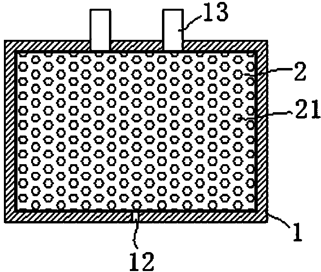
[0026] Embodiment 2: as image 3 As shown, the difference from Embodiment 1 is that the air intake hole and the combustion hole are respectively arranged on the opposite side walls of the combustion device housing.

[0027] In other embodiments: the shape of the combustion device housing can also be replaced by a cylinder, T-shaped or other prismatic or special-shaped; the number of combustion holes is not limited to 100, and can also be set to be less than 100 or greater than 100, the number of combustion holes The arrangement can be linear or non-linear; the number of air intake holes can also be replaced by one or at least three; The hole can be set at any position and can be lowered by the pressure equalizing piece, so that the airflow blown out from the combustion hole is very stable; the pressure equalizing piece can also be processed by other methods, such as casting; the pressure equalizing piece can not only be a one-piece structure , can also be replaced by a split ...


PUM


Abstract

The invention provides a gas eddy preventing combustion device which comprises a combustion device shell. A combustion gas containing cavity is formed in the combustion device shell; a plurality of combustion holes distributed in rows are formed in the combustion device shell; the combustion device is further provided with at least one gas inlet hole; the combustion gas containing cavity is filledwith pressure equalizing pieces; and a plurality of gas flow channels communicating with each other are formed among the pressure equalizing pieces or are arranged in the pressure equalizing pieces.The gas flow entering the combustion gas containing cavity eliminates the gas eddy by streaming in the gas flow channels, so that the gas quantity of each combustion hole is balanced with the gas pressure, and the purpose of stable production is achieved. The combustion device is used for producing quartz fiber yarns with filament diameters being 5 micrometers and below, so that the effects of stable operation, the low filament flying rate and the greatly improved yield are achieved.

Description

technical field [0001] The invention relates to an anti-gas swirl combustion device. Background technique [0002] Quartz fiber is drawn by melting quartz raw material at high temperature through a special combustion device. In the existing combustion device, the combustion gas first flows into a cavity through more than one air inlet, and then is sprayed out from the uniformly arranged combustion holes on the cavity. At this time, after the gas enters the cavity, vortex or turbulent flow will be generated, which will cause the gas ejected from the combustion hole to be unstable, which will cause the flame size of each combustion hole to be different, resulting in uneven melting temperature of raw materials, which will affect the operation stability. problem. Contents of the invention [0003] The invention proposes an anti-gas swirl combustion device to solve the technical problem that the gas in the inner chamber of the existing combustion device forms swirl and turbul...

Claims


Application Information

Patent Timeline
Patent Type & Authority Applications(China)
IPC IPC(8): F23D14/00F23D14/46
CPCF23D14/00F23D14/46
Inventor 李泉涌
Owner 河南神玖天航新材料股份有限公司
Why Eureka
Try Eureka