Self-walking type shield tunneling machine

A self-propelled, shield machine technology, applied in the direction of shaft lining, tunnel lining, underground chamber, etc., can solve the problems of tediousness and increase of project cost, so as to improve economic benefits, reduce workload, avoid tediousness and waste of manpower Effect

Pending Publication Date: 2019-10-08
HUNAN UNIV +1
View PDF0 Cites 2 Cited by
  • Summary
  • Abstract
  • Description
  • Claims
  • Application Information

AI Technical Summary

Problems solved by technology

In addition, the segment assembly process of the traditional pipe jacking machine is relatively cumbersome, and transportation from other places will also increase the cost of the entire project

Method used


Image

  • Self-walking type shield tunneling machine
  • Self-walking type shield tunneling machine
  • Self-walking type shield tunneling machine

Examples


Embodiment Construction

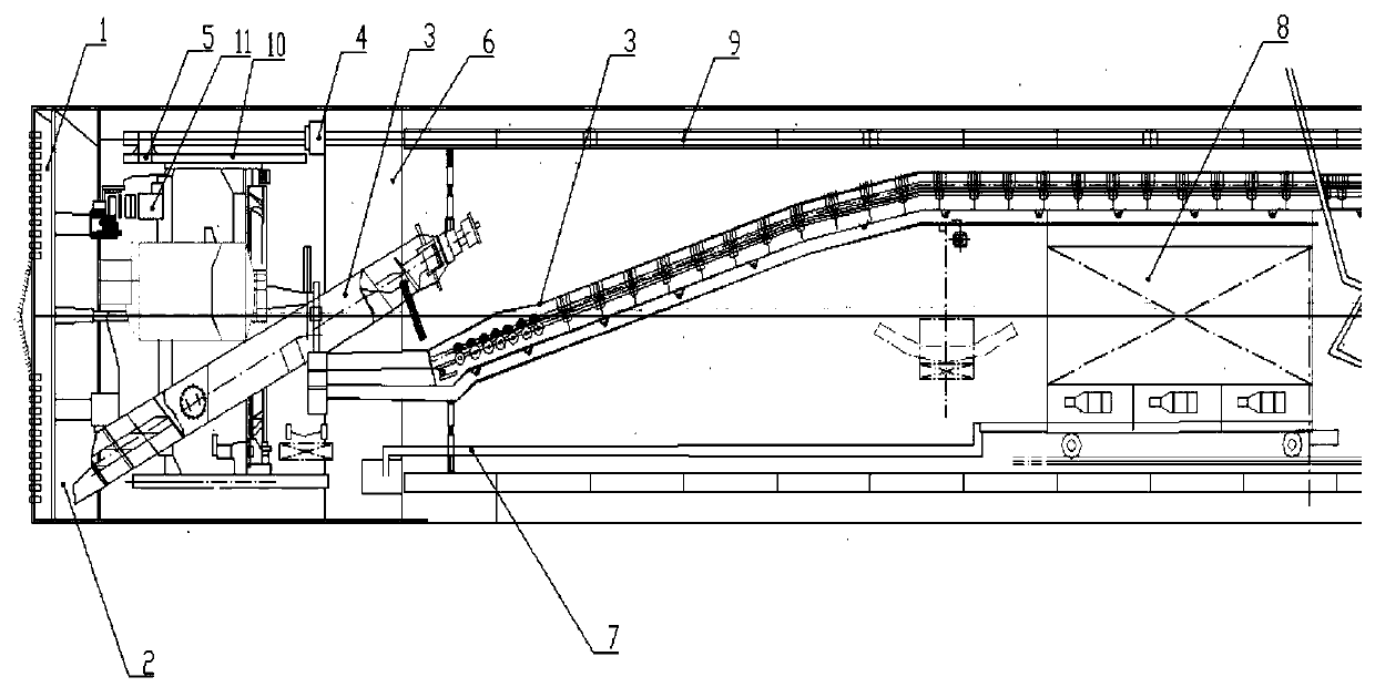
[0030] refer to figure 1 and figure 2 The present invention is a self-propelled shield machine, which includes a cutting and stirring structure 1, a cutter head power structure 2, a mud inlet and discharge structure 3, a pipeline sliding form casting structure 4 and a self-propelled structure 5 arranged in the front shell; The cutting and stirring structure 1 includes a cutterhead structure for cutting soil, a stirring rod connected to the cutterhead structure, and a compartment plate, and a sealing soil for collecting cutting rock and soil is formed between the cutterhead structure and the compartment plate bin, the stirring rod is used to stir the cutting rock and soil in the sealed soil bin when the cutter head structure rotates; the cutter head power structure 2 includes a reducer, a power box pinion connected with the reducer and the The large gear connected to the pinion of the power box; the mud inlet and discharge structure 3 includes a screw conveyor with an entranc...


PUM


Abstract

The invention discloses a self-walking type shield tunneling machine which comprises a cutting stirring structure, a cutter power structure, a mud feeding and discharging mechanism, a pipeline slidingdie pouring structure and a self-walking structure. The cutting stirring structure, the cutter power structure, the mud feeding and discharging mechanism, the pipeline sliding die pouring structure and the self-walking structure are arranged in a front shell. The cutting stirring structure comprises a cutter structure used for cutting soil, a stirring bar and a bin partition plate. A sealing soilbin used for collecting cutting rock soil is formed between the cutter structure and the bin partition plate. The stirring bar is used for stirring the cutting rock soil in the sealing soil bin whenthe cutter structure rotates. The mud feeding and discharging structure comprises a screw conveyor with an inlet formed in the lower portion of the sealing soil bin, a material conveying belt, a waterfeeding pipe and a water discharging pipe. The self-walking structure comprises an axial hydraulic movement structure, a steel pipe pre-fixed in the sliding die pouring structure and a clamping leg structure used for applying clamping force to the steel pipe. The self-walking type shield tunneling machine more superior and more practical is provided, and meanwhile, the sliding die pouring technology is used for further improving the work efficiency of the shield tunneling machine.

Description

technical field [0001] The invention relates to the field of pipe jacking shield technology, in particular to a self-propelled shield machine for realizing on-site casting of pipeline sliding forms. Background technique [0002] With the development of my country's rail transit, the use of pipe jacking shield equipment is becoming more and more extensive, and the localization of pipe jacking shield equipment is becoming increasingly urgent. At present, my country's technical requirements for pipe jacking shield machines are also getting higher and higher. It is necessary While introducing advanced foreign pipe-jacking shield equipment, we will continue to strengthen technical strength in all aspects, and develop domestic pipe-jacking shield machines suitable for my country's national conditions and different geological environments. However, at present, most of the pipe jacking shield machines in my country are pipe jacking type, and the self-propelled type is rarely seen. Ho...

Claims


Application Information

Patent Timeline
Patent Type & Authority Applications(China)
IPC IPC(8): E21D9/06E21D9/08E21D9/12E21D11/10
CPCE21D9/0609E21D9/0621E21D9/08E21D9/124E21D11/102E21D11/105
Inventor 卿启湘文桂林杨兴发曾嵘
Owner HUNAN UNIV
Why Eureka
Try Eureka