
Bladder electromyographic signal detecting device and detecting system

A technology of myoelectric signal and detection device, which is applied in the field of medical devices, can solve problems such as ineffective detection of bladder myoelectric signal, and achieve the effect of alleviating pain and low cost

Pending Publication Date: 2019-10-08
武汉闻道复兴智能科技有限责任公司
View PDF14 Cites 0 Cited by
  • Summary
  • Abstract
  • Description
  • Claims
  • Application Information

AI Technical Summary

Problems solved by technology

[0006] The technical problem to be solved by the present invention is to solve the problem that the bladder myoelectric signal cannot be effectively detected in the prior art

Method used


Image

  • Bladder electromyographic signal detecting device and detecting system
  • Bladder electromyographic signal detecting device and detecting system
  • Bladder electromyographic signal detecting device and detecting system

Examples


Embodiment 1

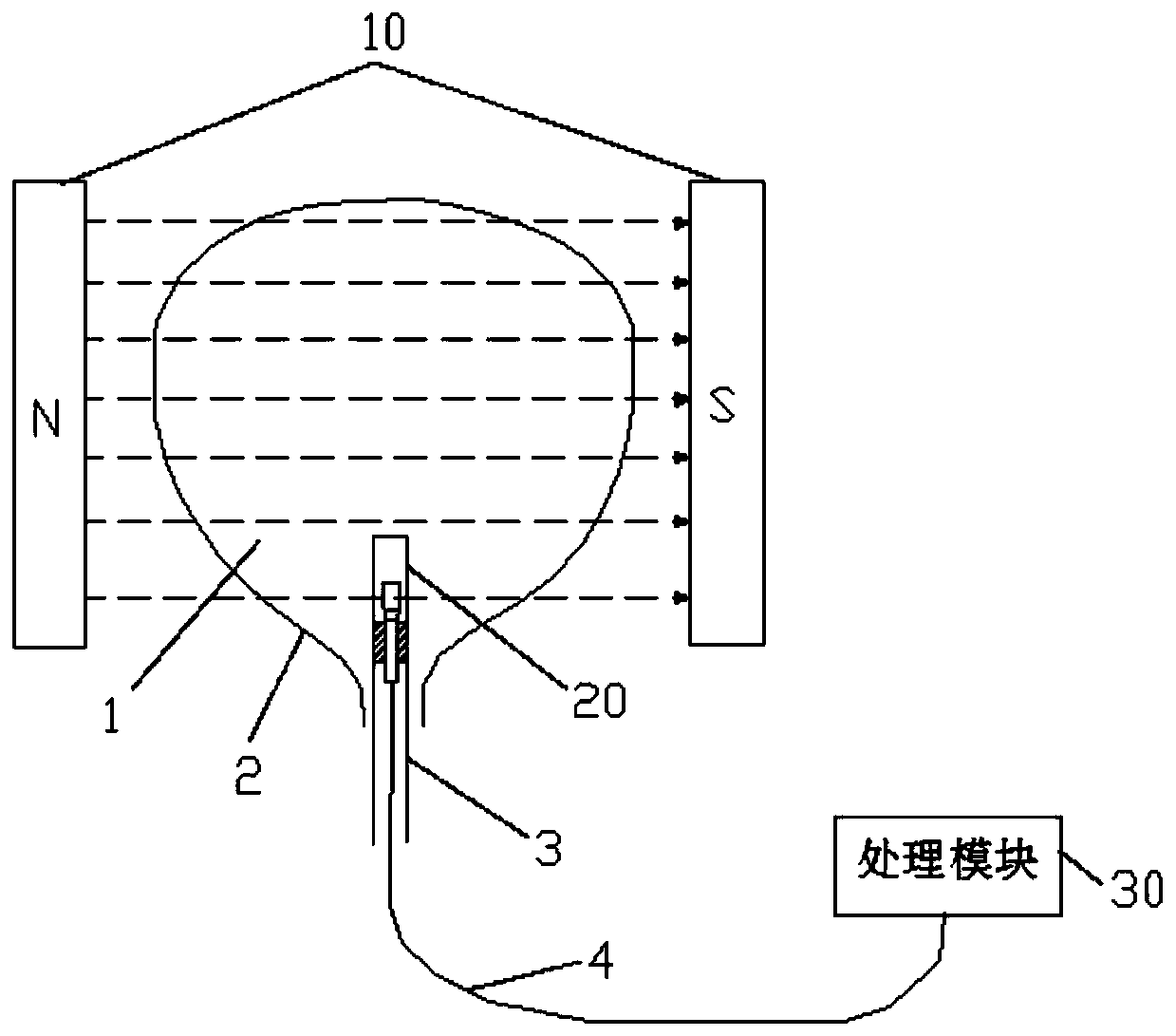
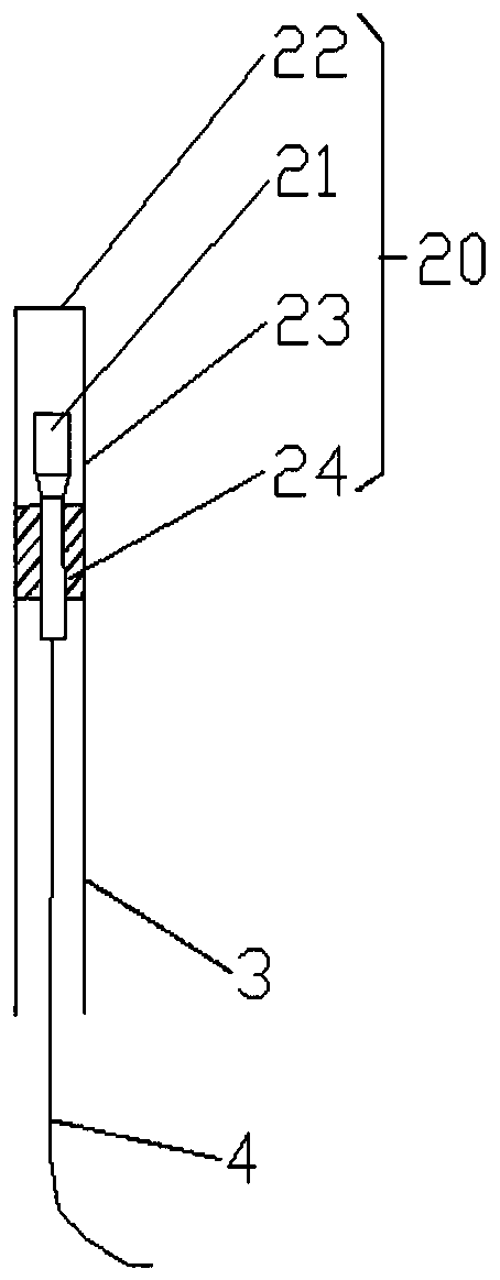
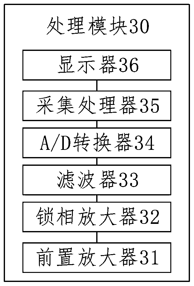
[0053] Embodiment 1 of the present invention provides a bladder myoelectric signal detection device, such as figure 1 with figure 2 As shown, the bladder myoelectric signal detection device includes: a wearable magnetic field generating device 10, a probe head 20 and a processing module 30;

[0054] The wearable magnetic field generating device 10 includes a magnetic generator array, and the magnetic generator array is used to generate an alternating magnetic field at the patient's bladder;

[0055] The probe 20 includes a high-sensitivity microphone 21, a diaphragm 22 and an air cavity sleeve 23, and the probe 20 is used to be inserted into the patient's bladder cavity 1; the high-sensitivity microphone 21 is arranged on the air cavity sleeve 23 Inside; the air cavity sleeve 23 is used to separate the high-sensitivity microphone 21 from the medium in the bladder cavity 1; the diaphragm 22 is arranged on the top of the air cavity sleeve 23 for sealing the The air cavity sle...

Embodiment 2

[0070] Embodiment 2 of the present invention provides a detection system, see Figure 6 to Figure 9 , comprising: the bladder myoelectric signal detection device, the bladder pressure detection device 40 and the urination device 50 described in any one of Embodiment 1 of the present invention;

[0071] The bladder pressure detection device 40 includes a urodynamic manometric tube 41 and a pressure sensor 42; the urodynamic manometric tube 41 is used to be set in the patient's bladder cavity 1, and the pressure sensor 42 is used to be set in the patient's bladder cavity 1 Outside: one end of the pressure sensor 42 is connected to the urodynamic pressure measuring tube 41, and the other end of the pressure sensor 42 is connected to the processing module 30, and the processing module 30 is used to calculate the bladder pressure;

[0072] The urination device 50 includes a urination tube 52 and a solenoid valve 51; the urination tube 52 is used to be arranged in the bladder cavity...


PUM


Abstract

The invention discloses a bladder electromyographic signal detecting device, which adopts a wearable magnetic field generating device to generate an alternating magnetic field in a bladder portion ofa patient, and uses a diaphragm on a detecting head to transmit an acoustic wave signal generated by the magnetoacoustic coupling effect in the bladder cavity, the acoustic wave signal is detected bya high-sensitivity microphone and converted into an electrical signal, and the electrical signal is processed by a processing module to obtain information of the bladder electromyographic signal, thebladder electromyographic signal can be effectively detected, non-invasive measurement is realized, the pain caused to patients is realized, and the cost of testing equipment is low. The invention also discloses a detection system, which uses the bladder pressure detecting device to detect the bladder pressure, and combines the bladder myoelectric signal, which can facilitate the doctor to intuitively analyze the relationship between the bladder contraction activity and the detrusor myoelectric activity. The detection system also includes an urination device that facilitates patient urinationduring the detection process.

Description

technical field [0001] The invention belongs to the technical field of medical devices, and more specifically relates to a bladder myoelectric signal detection device and a detection system. Background technique [0002] At present, the number of urinary system patients in my country is increasing year by year, among which patients with lower urinary tract dysfunction account for the vast majority. For male patients, it is mainly manifested as benign prostatic hyperplasia, and for women, it is mainly manifested as stress urinary incontinence. The higher the prevalence rate, the neurogenic bladder and low-compliance bladder have become a great problem for patients. In order to diagnose and study the symptoms of lower urinary tract dysfunction, there is an increasing demand for the detection of bladder EMG. In addition, for abnormal voiding function caused by neurological lesions, the detection of bladder myoelectric signals can prompt the existence of potential neurological l...

Claims


Application Information

Patent Timeline
IPC IPC(8): A61B5/0488A61B5/20
CPCA61B5/205A61B5/389
Inventor 胡忠民
Owner 武汉闻道复兴智能科技有限责任公司
Learn More