
Fuel cell stack

A fuel cell stack and single cell technology, which is applied to fuel cells, fuel cell components, circuits, etc., and can solve problems such as high manufacturing costs

Active Publication Date: 2019-10-01
HONDA MOTOR CO LTD
View PDF7 Cites 4 Cited by
  • Summary
  • Abstract
  • Description
  • Claims
  • Application Information

AI Technical Summary

Problems solved by technology

The sealing member uses elastic rubber seals such as fluorine-based and silicone, which has the problem of high manufacturing costs.

Method used


Image

  • Fuel cell stack
  • Fuel cell stack
  • Fuel cell stack

Examples


Embodiment Construction

[0035] Hereinafter, the fuel cell stack according to the present invention will be described with reference to the drawings by citing preferred embodiments.

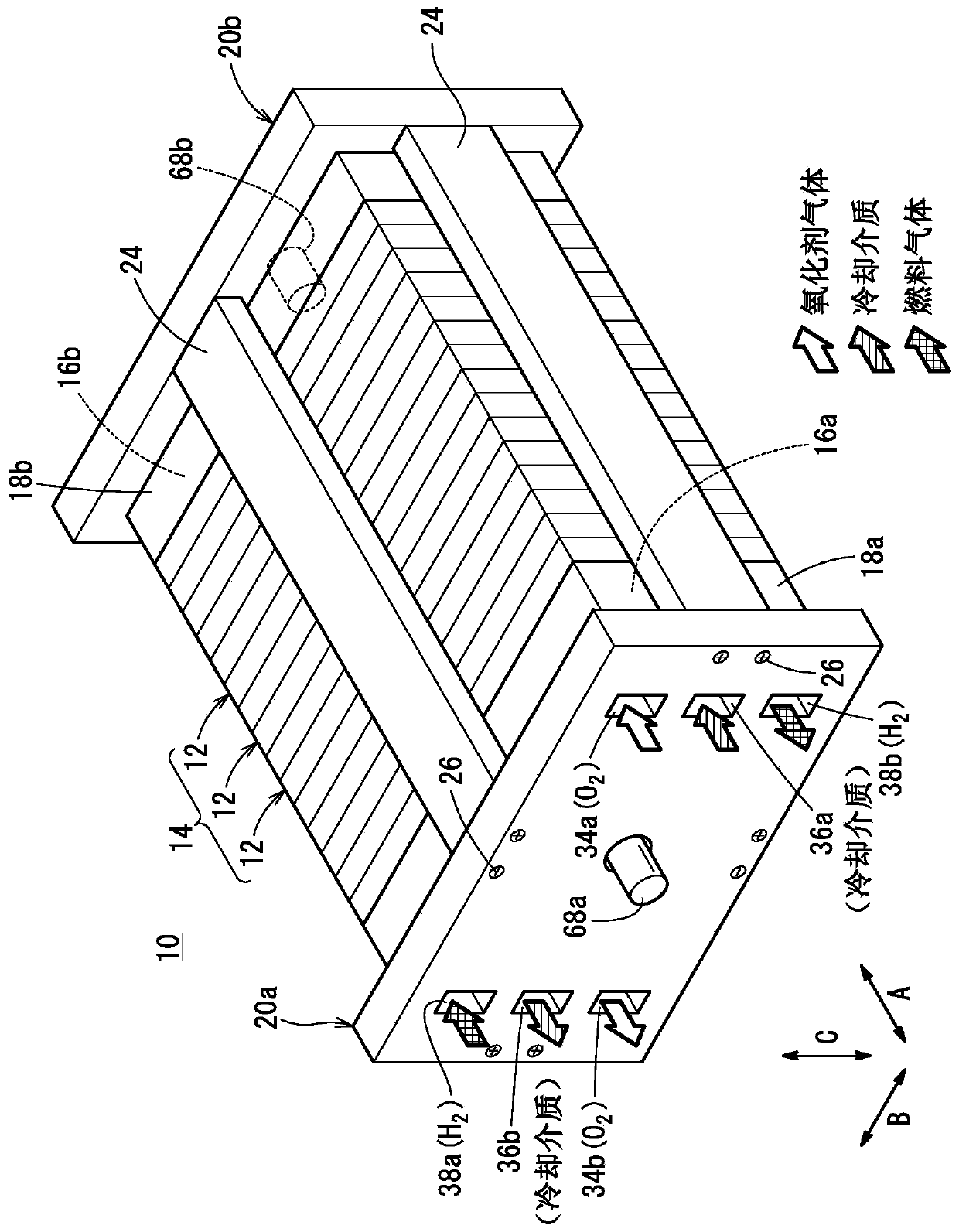
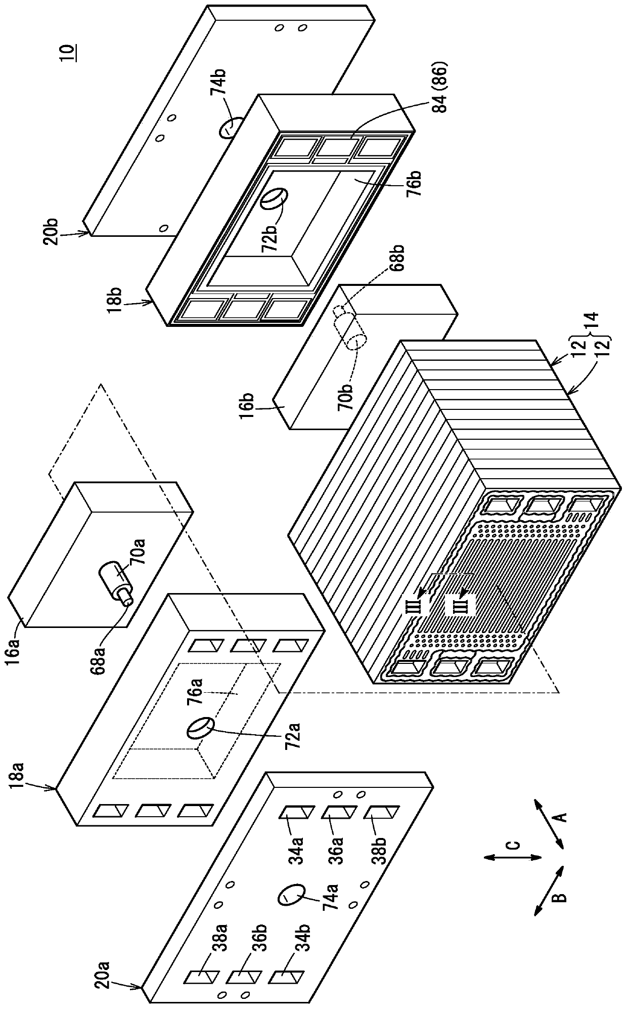
[0036] Such as figure 1 and figure 2 As shown, the fuel cell stack 10 according to one embodiment of the present invention includes a stacked body 14 in which a plurality of power generating cells 12 are stacked in the horizontal direction (arrow A direction). In addition, a plurality of power generating cells 12 may be stacked in the direction of gravity (direction of arrow symbol C). The fuel cell stack 10 is mounted, for example, on a fuel cell vehicle such as a fuel cell electric vehicle (not shown).

[0037] exist figure 2 Among them, the terminal plate 16a, the insulator 18a, and the end plate 20a are sequentially arranged outwardly at one end in the stacking direction (direction of arrow A) of the laminated body 14 . At the other end in the lamination direction of the laminated body 14, the terminal plate 16...


PUM


Abstract

The disclosure relates to a fuel cell stack (10) that includes a stack body (14) formed by stacking a plurality of power generation cells (12). A first seal line (52) of a first metal separator (30) and a second seal line (62) of a second metal separator (32) protrude in a stacking direction of the stack body (14) in a manner to contact a resin film (46). An insulator (18a) is provided with a first elastic seal member (80) which contacts a second end seal line (62e). The width (W2) of the first elastic seal member (80) is larger than the maximum width (W3) of the second end seal line (62e).

Description

technical field [0001] The present invention relates to a fuel cell stack comprising a laminated body in which a plurality of power generating cells are stacked. The power generating cells have an electrolyte membrane-electrode structure formed by arranging electrodes on both sides of an electrolyte membrane, and Metal separators arranged on both sides of the membrane-electrode structure. Background technique [0002] For example, a solid polymer fuel cell includes an electrolyte membrane-electrode structure (MEA) in which an anode electrode is disposed on one surface of an electrolyte membrane formed of a polymer ion exchange membrane, A cathode electrode is arranged on the other surface. The electrolyte membrane-electrode structure is sandwiched between separators (bipolar plates), thereby constituting a power generating unit cell. A fuel cell stack including a stack in which a predetermined number of power generating cells are stacked is incorporated in, for example, a ...

Claims


Application Information

Patent Timeline
Patent Type & Authority Applications(China)
IPC IPC(8): H01M8/0273H01M8/1007H01M8/2465H01M8/2457
CPCH01M8/0273H01M8/1007H01M8/2465H01M8/2457H01M8/0206H01M8/0254H01M8/0267H01M8/0276H01M8/2483H01M8/248H01M2008/1095Y02E60/50H01M8/242H01M8/2459H01M8/0247H01M8/0297
Inventor 池田佑太井上直树吉泽洋介和田真史
Owner HONDA MOTOR CO LTD
Learn More