Wireless test method for clock frequency of identification tag chip
A technology for clock frequency and wireless testing, which is applied in near-field transmission systems, read/write/query/recognition near-field transmission systems, electrical components, etc. in radio frequency identification systems. and other issues to achieve accurate and effective test results, more accurate test results, and reduced chip area
- Summary
- Abstract
- Description
- Claims
- Application Information
AI Technical Summary
Problems solved by technology
Method used
Image
Examples
specific Embodiment
[0053] The reader is an NI device, the model is PXIe-1062Q. This device can realize traversal and send TRcal of different lengths, and can test the frequency value BLF_test of the signal returned by the tag.
[0054] The reader-writer antenna adopts a circularly polarized antenna, and is connected to the reader-writer through a wired cable.
[0055]The test samples provided in this embodiment are one single-clock algorithm chip and one five-clock algorithm chip, both chips are packaged with antennas to form a single-clock algorithm label and a five-clock algorithm label.
Embodiment 1
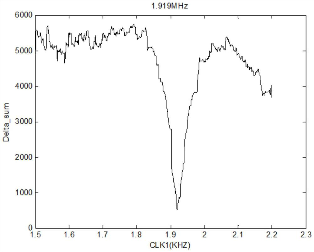
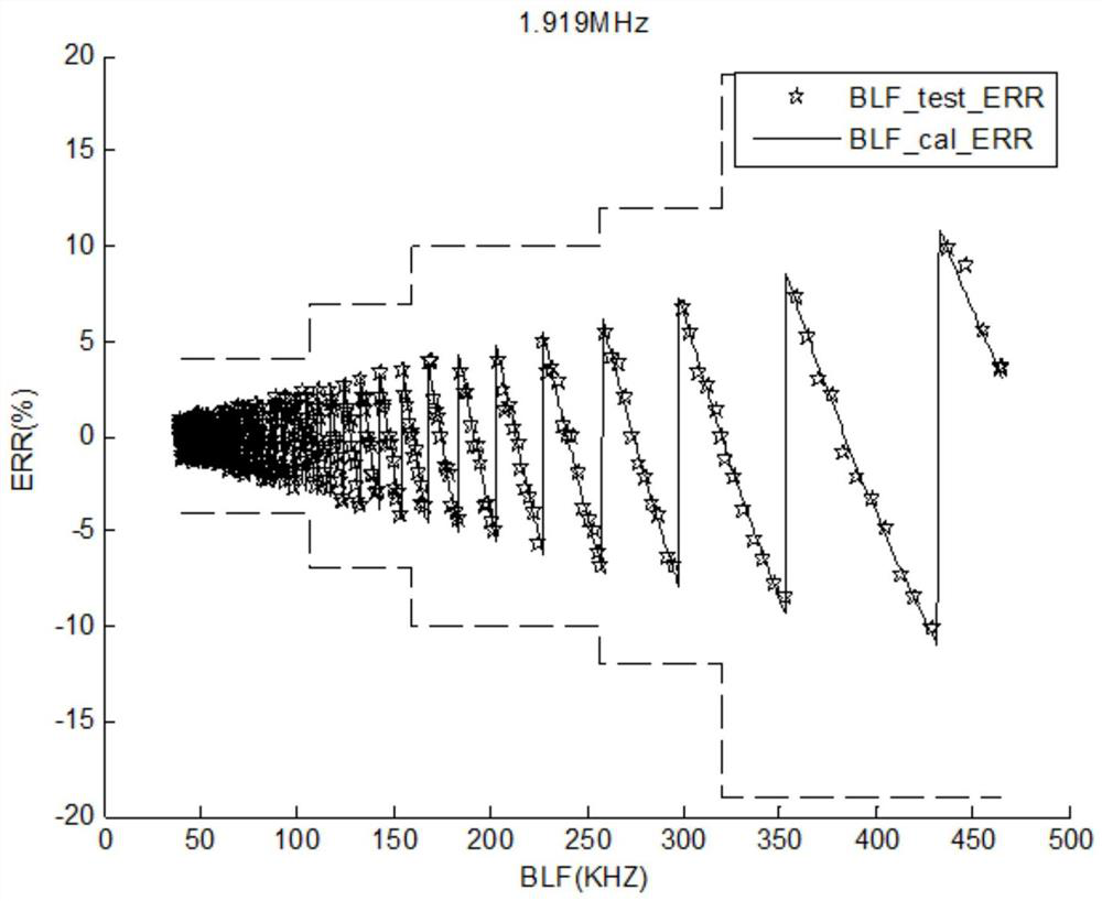
[0056] Embodiment 1, single clock algorithm chip clock test.
[0057] The chip clock is CLK1, and the number of clocks is n=1. The algorithm for calculating the BLF of the known chip is BLF_cal=f1(TRcal, DR, CLK1), and the formula f1 includes the influence of the internal sampling clock of the chip and the asynchronous transmission signal of the reader.
[0058] Use NIPXIe-1062Q to transmit Query commands with different TRcal lengths, and test the average frequency value of the returned signal. The test condition is DR==8, and the total test count=507 times.
[0059]
[0060]
[0061] The above is part of the data obtained from the test, and the total data has 507 rows.
[0062] The known function is BLF_cal=f1(TRcal, DR, CLK1), and the following formula can be listed according to the f1 function. According to the parameter traversal method, the following equations can be listed.
[0063] [BLF_test–f1(TRcal,DR,CLK1)]^2=Delta
[0064] Put the data obtained from the tes...
Embodiment 2
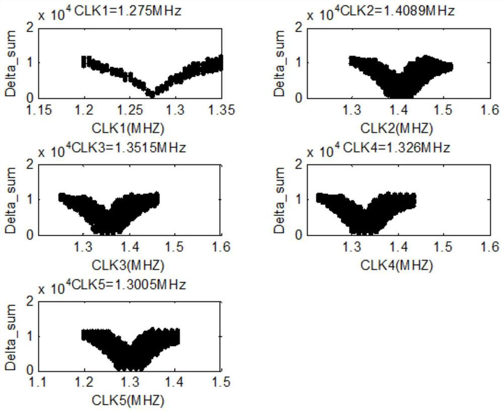
[0079] Embodiment 2, five-clock algorithm chip clock test.
[0080] The chip clocks are CLK1, CLK2, CLK3, CLK4, CLK5, and the number of clocks is n=5. It is known that the chip calculates the BLF algorithm as BLF_cal=f2(TRcal, DR, CLK1, CLK2, CLK3, CLK4, CLK5). The formula f2 includes the impact of the chip's internal sampling clock and the asynchronous signal emitted by the reader.
[0081] Use NIPXIe-1062Q to transmit Query commands with different TRcal lengths, and test the average frequency value of the returned signal. The test condition is DR==64 / 3, and the total test count=507 times.
[0082]
[0083]
[0084] The above is part of the data obtained from the test, and the total data has 507 rows.
[0085] The known function is BLF_cal=f2(TRcal, DR, CLK1, CLK2, CLK3, CLK4, CLK5), and the following formula can be listed according to the f2 function. According to the parameter traversal method, the following equations can be listed.
[0086] [BLF_test–f2(TRcal,DR,C...
PUM
 Abstract
Description
Claims
Application Information
 - R&D
- Intellectual Property
- Life Sciences
- Materials
- Tech Scout
- Unparalleled Data Quality
- Higher Quality Content
- 60% Fewer Hallucinations
Browse by: Latest US Patents, China's latest patents, Technical Efficacy Thesaurus, Application Domain, Technology Topic, Popular Technical Reports.
© 2025 PatSnap. All rights reserved.Legal|Privacy policy|Modern Slavery Act Transparency Statement|Sitemap|About US| Contact US: help@patsnap.com


