
Glass crusher

A glass breaking and crusher technology, which is applied in the field of mechanical devices, can solve the problems of glass debris splashing, damage to human physical and mental health, and insecurity, and achieve the effects of avoiding splashing, improving safety performance, and promoting crushing.

Pending Publication Date: 2019-09-27
江苏耀北玻璃科技有限公司
View PDF0 Cites 4 Cited by
  • Summary
  • Abstract
  • Description
  • Claims
  • Application Information

AI Technical Summary

Problems solved by technology

Existing hammer crushers are crushed by beating, which will cause glass debris to splash around during the crushing process, which will damage the physical and mental health of the human body and cause many unsafe factors.

Method used


Image

  • Glass crusher
  • Glass crusher

Examples


Embodiment Construction

[0009] The present invention will be further described below in conjunction with the accompanying drawings and specific embodiments.

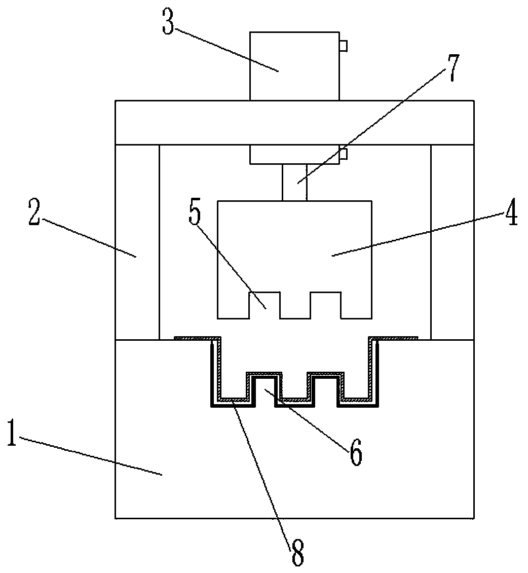
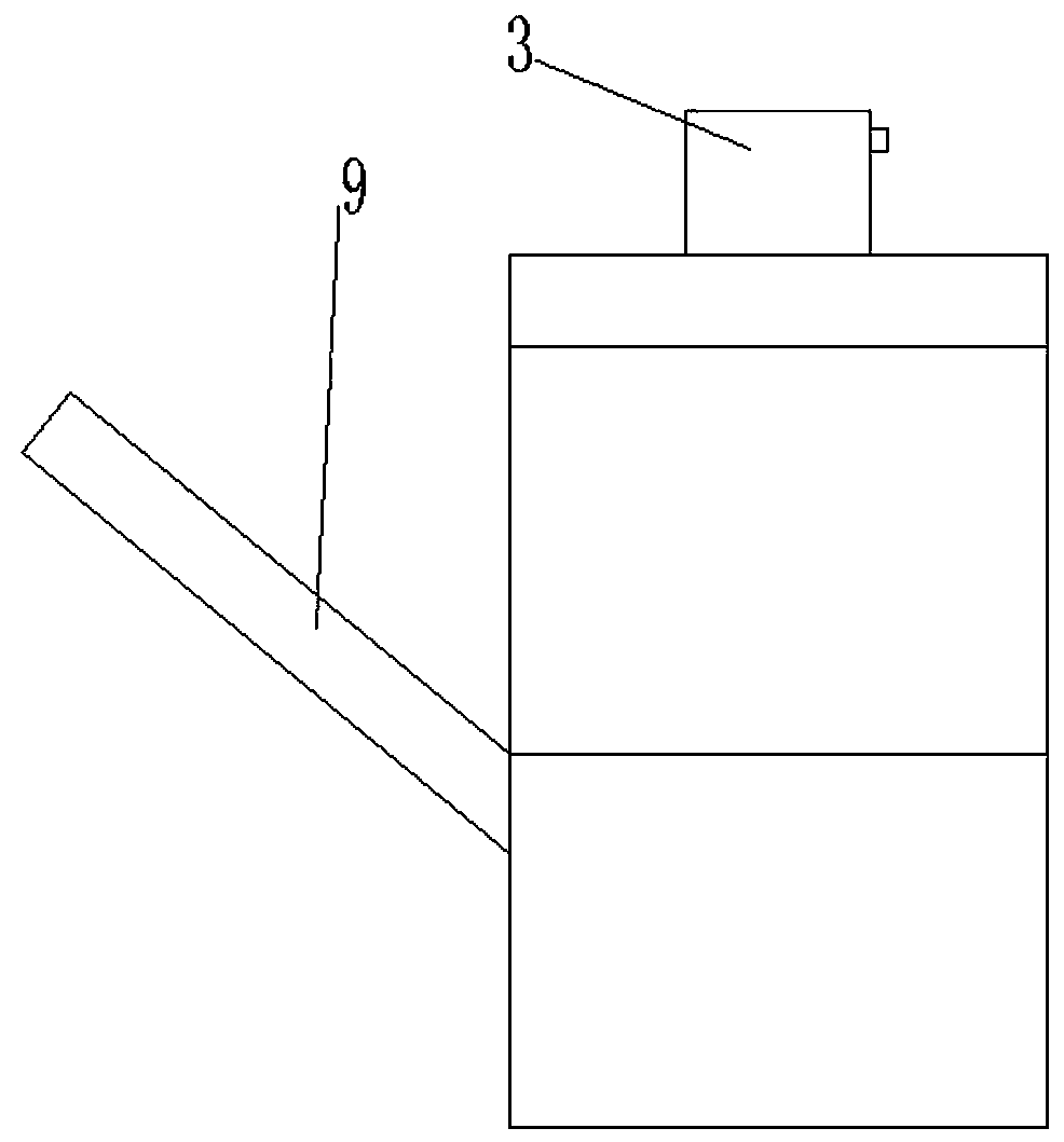
[0010] figure 1 , 2 Middle: machine base 1, frame 2, oil cylinder 3, upper mold 4, groove 5, convex body 6, moving plunger 7, iron plate 8, feeding slide plate 9.

[0011] A glass breaker, comprising a base 1, a frame 2 welded to the base 1, the glass breaker also includes an oil cylinder 3, an upper die 4, and the upper die 4 is provided with a serrated groove 5 , specifically, the groove 5 is in the shape of a rectangular tooth. The base 1 is provided with a convex body 6, the groove 5 and the convex body 6 are engaged up and down, and a large batch of large glass is put between the groove 5 and the convex body 6, and the moving plunger of the oil cylinder 3 The up and down telescopic movement drives the upper mold 4 to perform the up and down extrusion stroke movement, and exerts pressure and bending external force on the glass during the...


PUM


Abstract

The invention provides a glass crusher. A machine base and a rack fixedly connected with the machine base are included. The glass crusher further comprises an oil cylinder and an upper die, the upper die is provided with a sawtooth-shaped groove, and the machine base is provided with a protruding body engaged with the groove. The glass crusher has the beneficial effects that all-around splashing of glass fragments in the crushing process is avoided, and safety performance is greatly improved.

Description

technical field [0001] The invention relates to a mechanical device, in particular to a glass breaker. Background technique [0002] Waste glass is a kind of waste garbage, which is in the process of melting and recasting glass. Large pieces of glass need to be broken so that they can be put into the furnace for further processing operations. Existing hammer crushers are crushed by beating, which will cause glass fragments to splash around during the crushing process, which will damage the physical and mental health of the human body and cause many unsafe factors. Contents of the invention [0003] The invention provides a glass crusher, which adopts a crushing method of pressure application, avoids glass fragments splashing everywhere during the crushing process, and greatly improves safety performance. [0004] The present invention provides the following technical solutions: a glass breaker, including a machine base 1, a frame 2 fixedly connected with the machine base...

Claims


Application Information

Patent Timeline
Patent Type & Authority Applications(China)
IPC IPC(8): B02C1/00
CPCB02C1/005B02C2201/06
Inventor 武双喜吴秦辉
Owner 江苏耀北玻璃科技有限公司
Learn More