Collimating lens, laser module, depth camera and electronic device

A lens and collimation technology, which is applied in the field of collimation lenses, can solve problems affecting the imaging accuracy of depth images and calculation errors of depth cameras, and achieve the effects of reducing process complexity, ensuring yield, and improving competitiveness

Inactive Publication Date: 2019-09-24
GUANGDONG OPPO MOBILE TELECOMM CORP LTD
View PDF9 Cites 3 Cited by
  • Summary
  • Abstract
  • Description
  • Claims
  • Application Information

AI Technical Summary

Problems solved by technology

However, as the temperature in the use environment changes, the focal length of the lens will also change greatly, resulting in significant changes in the field of view and spot size of the light information emitted from the lens and projected to the measured object, which further leads to depth Errors occur in the calculation of the camera, which affects the imaging accuracy of the depth image

Method used


Image

  • Collimating lens, laser module, depth camera and electronic device
  • Collimating lens, laser module, depth camera and electronic device
  • Collimating lens, laser module, depth camera and electronic device

Examples


no. 1 example

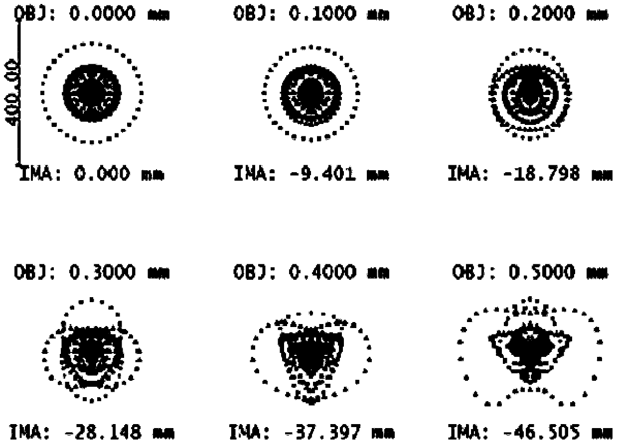
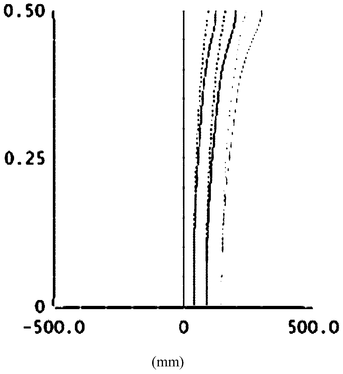
[0056] see Figure 1 to Figure 4 , in the collimating lens 11 of the first embodiment, the effective focal length f=4.267mm of the collimating lens 11 when the temperature is -15 degrees (°), and the effective focal length f=4.264mm when the temperature is 60 °; the focal length f The focal length change within the temperature range [-15°, 60°] is within 0.003mm, and it has good temperature change stability.

[0057] The total optical length of the collimating lens 11 (that is, the distance from the object plane S0 to the image side S8 of the fourth lens L4 on the optical axis) TTL=3.400 mm. The numerical aperture NA of the collimator lens 11 is 0.18mm.

[0058] The collimating lens 11 satisfies the following conditions: TTL / f=0.797; f4 / f1=1.572; f4 / f2=-3.368; f4 / f3=0.698; f / R8=-3.416; R1 / R8=-0.813; CT4 / CT2 = 1.847. The collimating lens 11 also meets the conditions of the following table:

[0059] Table I

[0060]

[0061]

[0062] Table 2

[0063]

no. 2 example

[0065] see figure 1 , Figure 5 to Figure 7 , in the collimating lens 11 of the first embodiment, the effective focal length f=3.989mm of the collimating lens 11 when the temperature is -15 degrees (°), and the effective focal length f=3.988mm when the temperature is 60 °; the focal length f When the focal length changes within the temperature range [-15°, 60°] within 0.001mm, it has good temperature change stability.

[0066] The total optical length of the collimating lens 11 (that is, the distance from the object plane S0 to the image side S8 of the fourth lens L4 on the optical axis) TTL=3.295mm. The numerical aperture NA of the collimator lens 11 is 0.18mm.

[0067] The collimating lens 11 satisfies the following conditions: TTL / f=0.826; f4 / f1=1.914; f4 / f2=-3.234; f4 / f3=0.698; f / R8=-3.155; R1 / R8=-0.803; CT4 / CT2 = 1.914. The collimating lens 11 also meets the conditions of the following table:

[0068] table 3

[0069]

[0070] Table 4

[0071]

[0072] see f...


PUM


Abstract

The invention discloses a collimating lens, a laser module, a depth camera and an electronic device. The collimating lens sequentially comprises a first lens with positive focal power, a second lens with negative focal power, a third lens with positive focal power and a fourth lens with positive focal power from an object side to an image side. The object side surface and the image side surface of the first lens are convex surfaces. The object side surface and the image side surface of the second lens are concave surfaces. The object side surface of the third lens is a concave surface, and the image side surface of the third lens is a convex surface. The object side surface of the fourth lens is a concave surface, and the image side surface of the fourth lens is a convex surface. The first lens, the second lens and the third lens are all plastic lenses, the fourth lens is a glass lens, and the object side surfaces and the image side surfaces of the first lens to the fourth lens are aspheric surfaces. The collimating lens, the laser module, the depth camera and the electronic device effectively control the change of focal lengths at different temperatures through the matching design of the surface types and materials of the first to fourth lenses, thereby guaranteeing the imaging precision of depth images at different temperatures.

Description

technical field [0001] The present application relates to collimating lens technology, in particular to a collimating lens, a laser module, a depth camera and an electronic device. Background technique [0002] In the current 3D structured light depth camera, the laser emitter emits laser light, the laser beam is collimated by the collimator lens and shoots to the target object, the laser light is reflected by the target object and then received by the depth camera to form a speckle image, and according to the speckle image and A depth image is generated from a reference image. However, as the temperature in the use environment changes, the focal length of the lens will also change greatly, resulting in a significant change in the field of view and spot size of the light information projected from the lens to the object under test, which further leads to depth An error occurs in the calculation of the camera, which affects the imaging accuracy of the depth image. Contents...

Claims


Application Information

Patent Timeline
Patent Type & Authority Applications(China)
IPC IPC(8): G01S17/89G01S7/481G02B13/18G02B13/14G02B1/04G02B1/00H04N5/225
CPCG01S17/89G01S7/481G02B13/004G02B13/008G02B1/041G02B1/00H04N23/55
Inventor 徐青
Owner GUANGDONG OPPO MOBILE TELECOMM CORP LTD
Why Eureka
Try Eureka