
Mold

A technology of mold and back mold

Pending Publication Date: 2019-09-24
QINGLING MOTORS GRP +1
View PDF0 Cites 1 Cited by
  • Summary
  • Abstract
  • Description
  • Claims
  • Application Information

AI Technical Summary

Problems solved by technology

[0003] In view of the above-mentioned shortcomings of the prior art, the purpose of the present invention is to provide a mold for solving the problems in the prior art that the ejector parts of the mold are easy to be stuck, strained, etc.

Method used


Image

  • Mold
  • Mold
  • Mold

Examples


Embodiment Construction

[0029] Embodiments of the present invention are described below through specific examples, and those skilled in the art can easily understand other advantages and effects of the present invention from the content disclosed in this specification. The present invention can also be implemented or applied through other different specific implementation modes, and various modifications or changes can be made to the details in this specification based on different viewpoints and applications without departing from the spirit of the present invention.

[0030] It should be noted that terms such as "upper", "lower", "left", "right", "middle" and "one" quoted in this specification are only for the convenience of description and are not intended to be used. To limit the practicable scope of the present invention, the change or adjustment of the relative relationship shall also be regarded as the practicable scope of the present invention without substantially changing the technical conte...


PUM


Abstract

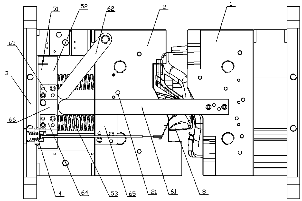
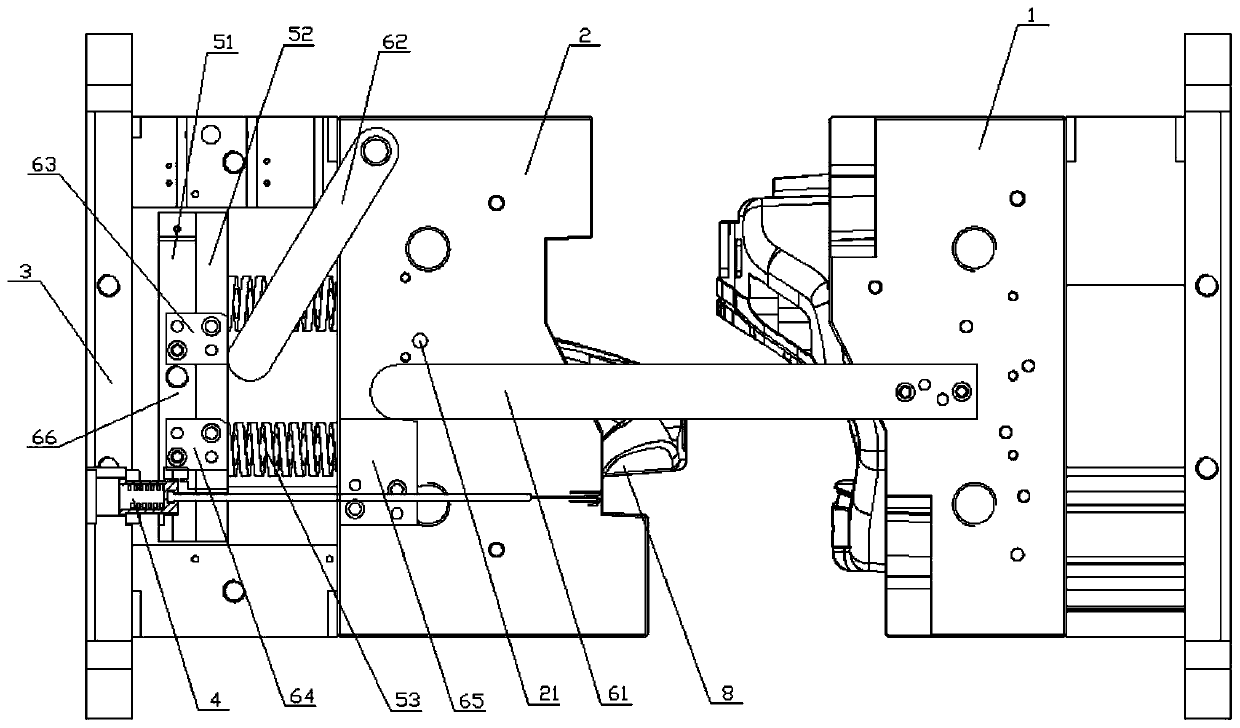
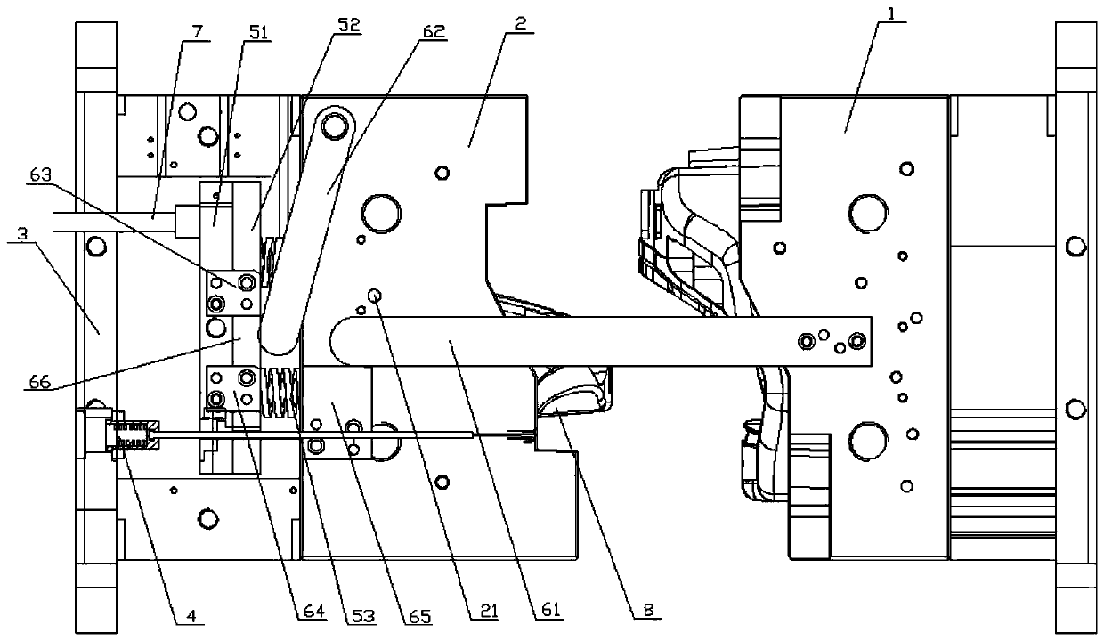
The invention relates to the field of molds, in particular to a mold with two-time ejection and resetting functions. The mold comprises a reset mechanism, an installing plate, a front mold and a back mold located between the installing plate and the front mold. A first-time ejection mechanism for first-time ejection of a product inside the back mold is installed on the installing plate, a second-time ejection mechanism for second-time ejection of the product inside the back mold is arranged between the installing plate and the back mold, in the assembling process of the front mold and the back mold, the front mold is operated to drive the reset mechanism to push the first-time ejection mechanism and the second-time ejection mechanism to reset. The mold has the advantages that by arranging the first-time ejection mechanism and the second-time ejection mechanism which are operated independently, the product can be completely ejected out from the back mold in the two-time ejection process, the phenomenon that clamping and strain of an ejection piece are caused by the excessive long ejection stroke of a single ejection mechanism is avoided, the mold operation stability is improved, and the service life is prolonged.

Description

technical field [0001] The invention relates to the field of molds, in particular to a mold with secondary ejection and reset functions. Background technique [0002] In mold design, in order to ensure that complex products are ejected smoothly during the ejection process, the ejection structure of the mold is often designed according to the shape of the product. Especially in the mold used to produce plastic parts, because of the complex shape of the plastic parts, it is often necessary to use ejectors such as flat ejector pins and cylinders to eject the product, but such ejectors such as flat ejector pins and cylinders are in the ejector In the case of a long ejection distance, it is easy to cause problems such as flat ejector pins, cylinders and other ejectors being strained or even stuck during the movement, which seriously affects product production efficiency and mold service life. Contents of the invention [0003] In view of the above-mentioned shortcomings of the...

Claims


Application Information

Patent Timeline
IPC IPC(8): B29C45/40B29C33/44
CPCB29C45/4005B29C33/44
Inventor 王纯东陈强陈旭峰郑琴
Owner QINGLING MOTORS GRP
Learn More