
Truss type machine tool feeding and blanking robot system and control method thereof

A robot system, truss-type technology, applied in the direction of program-controlled manipulators, manipulators, manufacturing tools, etc., can solve the problems of continuous positioning and grasping of the feeding tray, and achieve the effect of free switching

Inactive Publication Date: 2019-09-24
JIANGSU HAIYU MACHINERY +1
View PDF9 Cites 14 Cited by
  • Summary
  • Abstract
  • Description
  • Claims
  • Application Information

AI Technical Summary

Problems solved by technology

Since the shape of the ball cage part is generally called a bell shape with a thin top and a thick bottom, and the thick end generally has an inner hole that needs to be chamfered, it often takes two processes to complete the machining of a finished product, causing the general truss robot to perform When the ball cage parts are loaded and unloaded automatically, they will encounter difficulties in the continuous positioning and grabbing of the loading tray and the switching of different processing procedures.

Method used


Image

  • Truss type machine tool feeding and blanking robot system and control method thereof
  • Truss type machine tool feeding and blanking robot system and control method thereof
  • Truss type machine tool feeding and blanking robot system and control method thereof

Examples


Embodiment Construction

[0028] In order to make the technical problems, technical solutions and advantages to be solved by the present invention clearer, the following will describe in detail with reference to the drawings and specific embodiments.

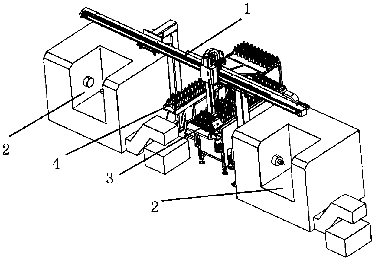
[0029] The invention provides a truss type machine tool loading and unloading robot system and a control method thereof.

[0030] Such as figure 1 As shown, the system includes a truss robot 1, a feeding tray 3, a feeding tray 4 and a CNC lathe 2, the loading tray 3 and the feeding tray 4 are located between two CNC machine tools 2, and the truss robot 1. The workpiece is transferred between the loading tray 3, the unloading tray 4 and the CNC machine tool 2; the truss robot 1 is composed of a rack and pinion, a reducer, a drive motor, a rotating mechanism and a pneumatic gripper. The pneumatic gripper There are two, namely the loading gripper and the unloading gripper; the two CNC machine tools 2 are respectively located at the lower left and lower rig...


PUM


Abstract

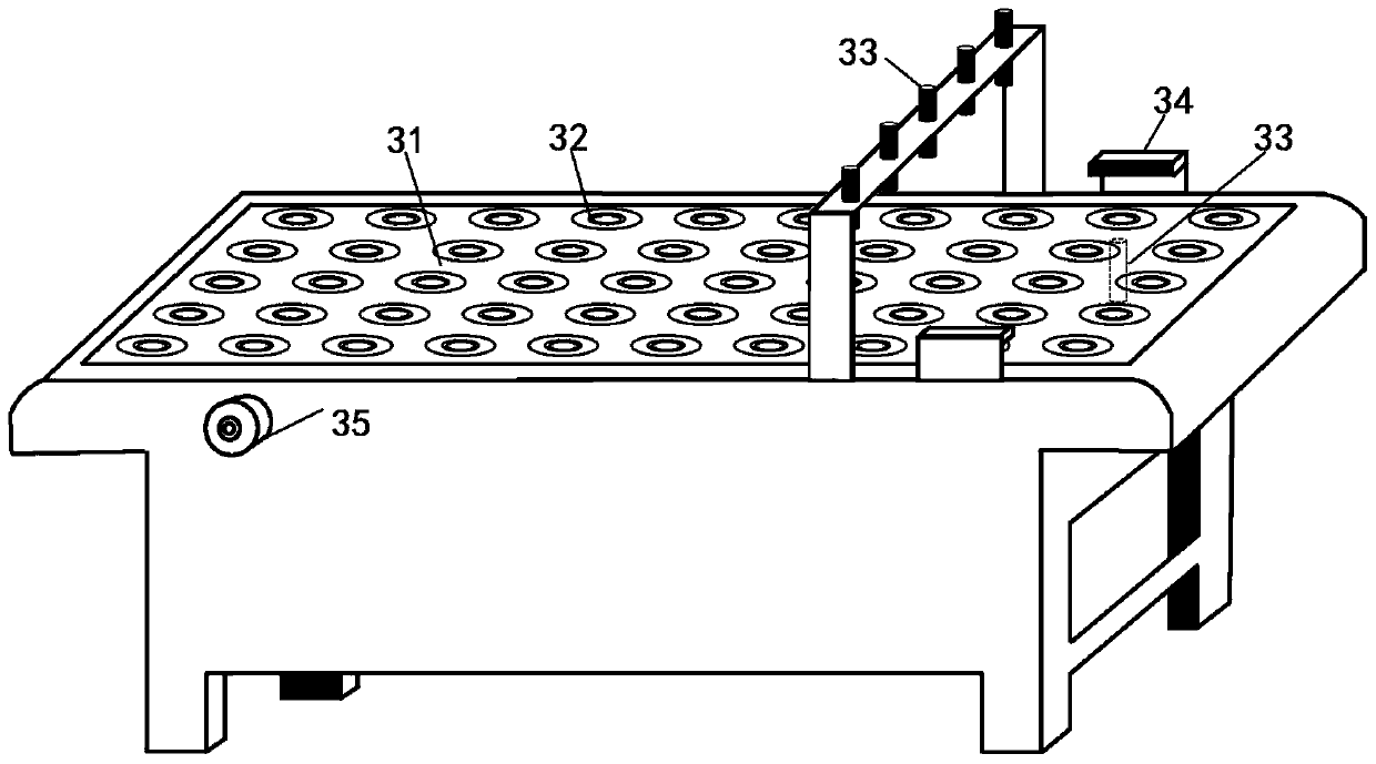
The invention provides a truss type machine tool feeding and blanking robot system and a control method thereof, and belongs to the technical field of machine tool automatic machining. The truss type machine tool feeding and blanking robot system comprises a truss type robot, a feeding material tray, a blanking material tray and numerical control machine tools, the feeding material tray and the blanking material tray are located between the two numerical control machine tools, the truss type robot is used for carrying out workpieces conveying between the feeding material tray, and the blanking material tray and the numerical control machine tools. The truss type robot adopts a four-degree-of-freedom structure, the truss type robot comprises a walking moving unit, a rotating unit, a grabbing unit and a control unit, wherein the feeding material tray is used for placing ball cage workpieces to be machined in batches, the blanking material tray adopts a frame type structure, the driving motor conveys the workpieces to a finished product centralized placing area according to the machining feeding material condition, and each the numerical control machine tool comprises a spindle box, a chuck, a feeding mechanism and a control system. According to the truss type machine tool feeding and blanking robot system and the control method thereof, through simple four-degree-of-freedom design and feeding and blanking process control, and the flexible switching of the free placement of the feeding material tray and the single-procedure machining and double-procedure machining of the ball cage can be realized.

Description

technical field [0001] The invention relates to the technical field of machine tool automatic processing, in particular to a truss type machine tool loading and unloading robot system and a control method thereof. Background technique [0002] CNC machine tools are key equipment widely used in the metal parts manufacturing and processing industry. They have high requirements for processing accuracy and processing efficiency. Most of the traditional methods use manual installation and disassembly of parts on the CNC machine tool, and complete the operation of the machine tool. The working environment of the operator is poor, the labor intensity is high, and the distance from the moving parts of the machine tool is close, which has potential safety hazards. With the development of digital control and information technology, the use of integrated equipment with few or no people to complete the loading and unloading of CNC machine tools can realize automatic production, which is...

Claims


Application Information

Patent Timeline
IPC IPC(8): B23Q7/04B23Q7/00B25J9/16
CPCB23Q7/003B23Q7/04B25J9/1602
Inventor 张勇军顾成义胡水平沈华宾张辉谢国兵肖雄米振莉郭强
Owner JIANGSU HAIYU MACHINERY
Learn More