Defrosting device of air conditioner evaporator

An evaporator and air conditioner technology, applied in air conditioning systems, space heating and ventilation, space heating and ventilation details, etc., can solve the problems of long downtime, temperature reduction, affecting user use, etc., to reduce downtime. Effect

Active Publication Date: 2019-09-20
海宁市耐得照明电器有限公司
View PDF6 Cites 4 Cited by
  • Summary
  • Abstract
  • Description
  • Claims
  • Application Information

AI Technical Summary

Problems solved by technology

[0003] However, since the temperature of the outdoor evaporator may reach below zero, frost will form on the surface. At this time, the air conditioner will stop for defrosting and then heat. , affecting the user's use of

Method used


Image

  • Defrosting device of air conditioner evaporator
  • Defrosting device of air conditioner evaporator
  • Defrosting device of air conditioner evaporator

Examples


Embodiment 1

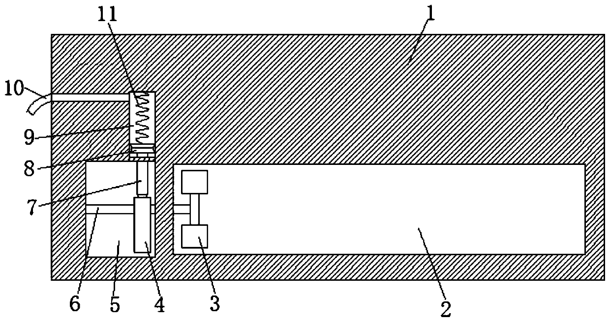
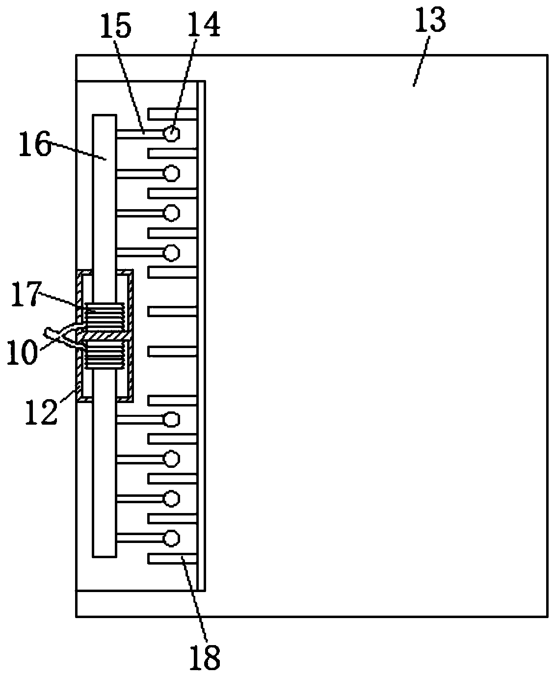
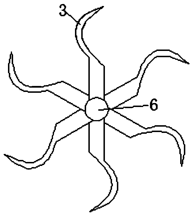
[0020] refer to Figure 1-3 , a defrosting device for an air conditioner evaporator. A device cavity 5 is provided on one side of the air outlet 2 of the air conditioner hanger body 1. The inner wall of the device cavity 5 is rotatably connected with a rotating rod 6, and one end of the rotating rod 6 extends to the air outlet 2. A wind wheel 3 is fixedly connected inside, a cam 4 is fixed on the rotating rod 6, a cavity 9 is arranged above the device cavity 5, and a push rod 7 is slidably connected between the cavity 9 and the device cavity 5. The lower end is abutted against the cam 4 through the roller, the upper end of the abutting rod 7 is installed with a piston 8, the piston 8 and the inner top of the cavity 9 are elastically connected by a spring 11, the inner wall of the cavity 9 is connected with a trachea 10, and inside the outer body 13 An evaporator 18 is installed, a device block 12 is installed on one side of the evaporator 18, and both ends of the device block ...

Embodiment 2

[0024] refer to Figure 4-5 The difference between this embodiment and the first embodiment is that the inner wall of the device cavity 5 is provided with a mounting groove 22, the opposite inner walls of the device cavity 5 are fixed with arc-shaped magnetic sheets 19, and the opposite sides of the two arc-shaped magnetic sheets 19 are The opposite poles attract each other. A coil 20 is installed on the outer side wall of the rotating rod 6. The coil 20 is located between the two arc-shaped magnetic sheets 19. Electric coils 23 are installed at both ends of the coil 20, and the opposite inner walls of the installation slot 22 are fixed with The brush 21 matched with the electric coil 23 is connected with a power transmission line 24 , and the two power transmission lines 24 are respectively connected with both ends of the evaporator 18 .

[0025] When the wind wheel 3 drives the rotating rod 6 to rotate, the coil 20 on the rotating rod 6 will rotate between the two arc-shaped...


PUM


Abstract

The invention discloses a defrosting device of an air conditioner evaporator. The defrosting device comprises an air conditioner hanging machine body and an outer machine body, a device cavity is formed in one side of an air outlet of the air conditioner hanging machine body, a rotating rod is rotationally connected to the inner wall of the device cavity, one end of the rotating rod extends into the air outlet and is fixedly connected with a wind wheel, a cam is fixed on the rotating rod, a cavity is formed above the device cavity, an abutting rod penetrates through the cavity and the device cavity in a penetrating manner, the lower end of the abutting rod abuts against the cam through a rolling wheel, a piston is arranged at the upper end of the abutting rod, the piston is elastically connected with the inner top of the cavity through a spring, an air pipe is connected to the inner wall of the cavity, and an evaporator is arranged in the outer machine body. The air conditioner is reasonable in structure, when the air conditioner works, all the evaporation iron sheets of the evaporator can be continuously impacted, so that frost on the surface of the evaporator can be effectively shocked, so that the shutdown time is greatly shortened.

Description

technical field [0001] The invention relates to the technical field of air conditioners, in particular to a defrosting device for an air conditioner evaporator. Background technique [0002] At present, air conditioners have become more and more popular. Air conditioners are mainly composed of on-hook and landline. The on-hook is installed indoors, and the landline is installed outdoors. When using an air conditioner for heating in winter, the gas freon is pressurized by the compressor to become a high temperature and high pressure gas, which enters the heat exchanger of the indoor unit (condenser at this time), condenses, liquefies and releases heat, turns into a liquid, and heats the indoor air at the same time. So as to achieve the purpose of increasing the indoor temperature. The liquid freon is decompressed by the throttling device and enters the heat exchanger of the outdoor unit (in this case, the evaporator), and evaporates and vaporizes to absorb heat and become a ...

Claims


Application Information

Patent Timeline
Patent Type & Authority Applications(China)
IPC IPC(8): F25B47/00F24F1/14F24F13/30
CPCF24F1/14F24F13/30F25B47/00
Inventor 陈亚军
Owner 海宁市耐得照明电器有限公司
Why Eureka
Try Eureka