Eureka AIR delivers breakthrough ideas for toughest innovation challenges, trusted by R&D personnel around the world.

Flight photographing positioning equipment, flight photographing positioning method and device, and storage medium

A technology of positioning equipment and positioning method, which is applied in the field of automation, can solve the problems that the positioning method is difficult to meet high-speed pick-and-place materials and precise positioning at the same time, cannot meet high-speed pick-and-place materials, and affects positioning accuracy, etc., to achieve high stability and high accuracy The effect of speeding up and speeding up the detection rate

Pending Publication Date: 2019-09-17
SHENZHEN JPT OPTO ELECTRONICS CO LTD
View PDF0 Cites 11 Cited by
  • Summary
  • Abstract
  • Description
  • Claims
  • Application Information

AI Technical Summary

Problems solved by technology

The former method cannot meet the needs of high-speed pick-and-place materials because the camera mechanism or the object under test needs to move and stop relatively; the latter method is for flying shooting, controlling the accuracy of the exposure time of the camera mechanism and the response delay of the camera mechanism. And the speed of flight will directly affect the position of the object to be measured in the field of view of the camera mechanism, and then affect the positioning accuracy
Therefore, traditional positioning methods are difficult to meet the requirements of high-speed pick-and-place and precise positioning at the same time

Method used


Image

  • Flight photographing positioning equipment, flight photographing positioning method and device, and storage medium
  • Flight photographing positioning equipment, flight photographing positioning method and device, and storage medium
  • Flight photographing positioning equipment, flight photographing positioning method and device, and storage medium

Examples


no. 1 example

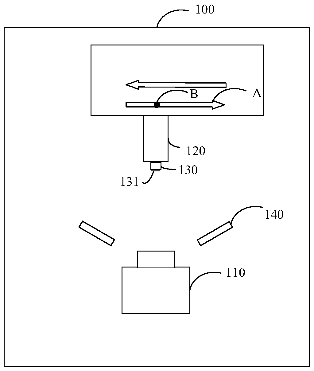
[0061] see figure 1 , figure 1 Shown is the flying shot positioning device 100 provided according to the first embodiment of the present application.

[0062] In this embodiment, the flying camera positioning device 100 may include a camera mechanism 110 , a transporting part 120 , and a nozzle head 130 . The suction nozzle head 130 is disposed on a side of the transporting part 120 facing the camera mechanism 110 .

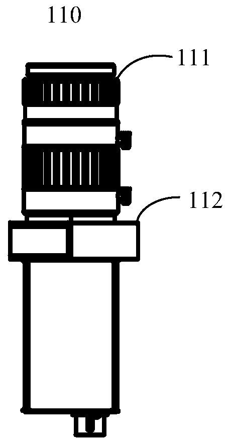
[0063] Wherein, the camera mechanism 110 may be a camera module, a camera, a camera, and the like. Please also refer to figure 1 and figure 2 , in this embodiment, in order to obtain better positioning images, the camera mechanism 110 may include a lens 111 and a body 112 . The lens 111 is connected to the body 112 and faces the delivery part 120 , so that the lens 111 acquires a frame including the delivery part 120 , so as to facilitate taking positioning images. The lens 111 can adopt a lens with a suitable focal length to shoot with a fixed focus, so a...

no. 2 example

[0109] see Figure 10 , in this embodiment, a flying camera positioning device 200 may also be provided. Since the flying camera positioning device 200 has many similarities with the flying camera positioning device 100 in terms of structure, connection relationship and function, please refer to the first embodiment for the parts with similar structures.

[0110] The flying camera positioning device 200 may include a camera 210 , a material transport mechanism 220 , and an auxiliary positioning member 230 . The auxiliary positioning member 230 is arranged on the side of the material transport mechanism 220 facing the camera 210 , and the material transport mechanism 220 is within the shooting range of the camera 210 .

[0111] In this embodiment, the structure, connection relationship and functions of the camera 210 can refer to the camera mechanism 110 of the flying camera positioning device 100 in the first embodiment; For the relationship and functions, please refer to th...


PUM


Abstract

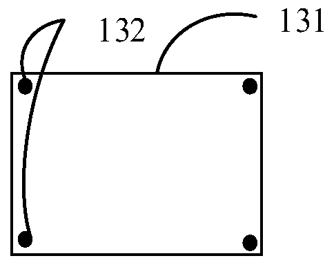
The invention provides flight photographing positioning equipment, a flight photographing positioning method and device, and a storage medium. The flight photographing positioning equipment comprises a camera mechanism, a material conveying piece, and a suction nozzle head, wherein the material conveying piece is opposite to the camera mechanism, and can move along a preset track; the suction nozzle head is arranged on the side of the material conveying piece facing the camera mechanism and moves with the material conveying piece, and positioning marks are arranged on a suction surface of the suction nozzle head; and the suction surface is located within a photographing range of the camera mechanism, the camera mechanism photographs the suction surface onto which a material is sucked, and the flight photographing positioning equipment determines the position of the material according to the positioning marks. The positioning marks are arranged on the suction surface of the flight photographing positioning equipment, and can be photographed during image photographing of the suction surface onto which the material is sucked, so that the flight photographing positioning equipment can carry out precise positioning on the material according to images. Therefore, the image photographing can be carried out on the material during high-speed material picking and placement; and although control precision requirements for exposure time of the camera mechanism are reduced and a wider delay range of the camera mechanism is allowed, the precise positioning of the material can still be achieved.

Description

technical field [0001] The present application relates to the field of automation, for example, to a flying camera positioning device, method, device and storage medium. Background technique [0002] In the automated production process, the positioning and adjustment of materials during automated material transportation is a very important link. At present, there are two main ways to locate the material: the object to be measured is still in the field of view of the camera mechanism, and the position information of the object to be measured is obtained; Realize the positioning of the object to be measured. The former method cannot meet the needs of high-speed pick-and-place materials because the camera mechanism or the object under test needs to move and stop relatively; the latter method is for flying shooting, controlling the accuracy of the exposure time of the camera mechanism and the response delay of the camera mechanism. And the speed of flight will directly affect ...

Claims


Application Information

Patent Timeline
Patent Type & Authority Applications(China)
IPC IPC(8): G01B11/00G01B11/24
CPCG01B11/002G01B11/24
Inventor 黄继欣
Owner SHENZHEN JPT OPTO ELECTRONICS CO LTD
Why Eureka
Eureka Blog
Learn More