Separation device and separation method

A separation device and separation method technology, applied in the directions of transportation and packaging, conveyor objects, etc., can solve the problems of low separation efficiency of the separation device, and achieve the effect of solving the low separation efficiency and improving the separation efficiency.

Pending Publication Date: 2019-09-17
MAIDER MEDICAL IND EQUIP
View PDF8 Cites 0 Cited by
  • Summary
  • Abstract
  • Description
  • Claims
  • Application Information

AI Technical Summary

Problems solved by technology

[0004] The main purpose of the present invention is to provide a separation device and a separation method to solve the technical problem that the separation efficiency of the separation device in the prior art is low

Method used


Image

  • Separation device and separation method
  • Separation device and separation method

Examples


Embodiment Construction

[0024] It should be noted that, in the case of no conflict, the embodiments in the present application and the features in the embodiments can be combined with each other. The present invention will be described in detail below with reference to the accompanying drawings and examples.

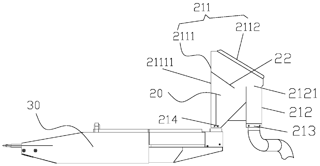
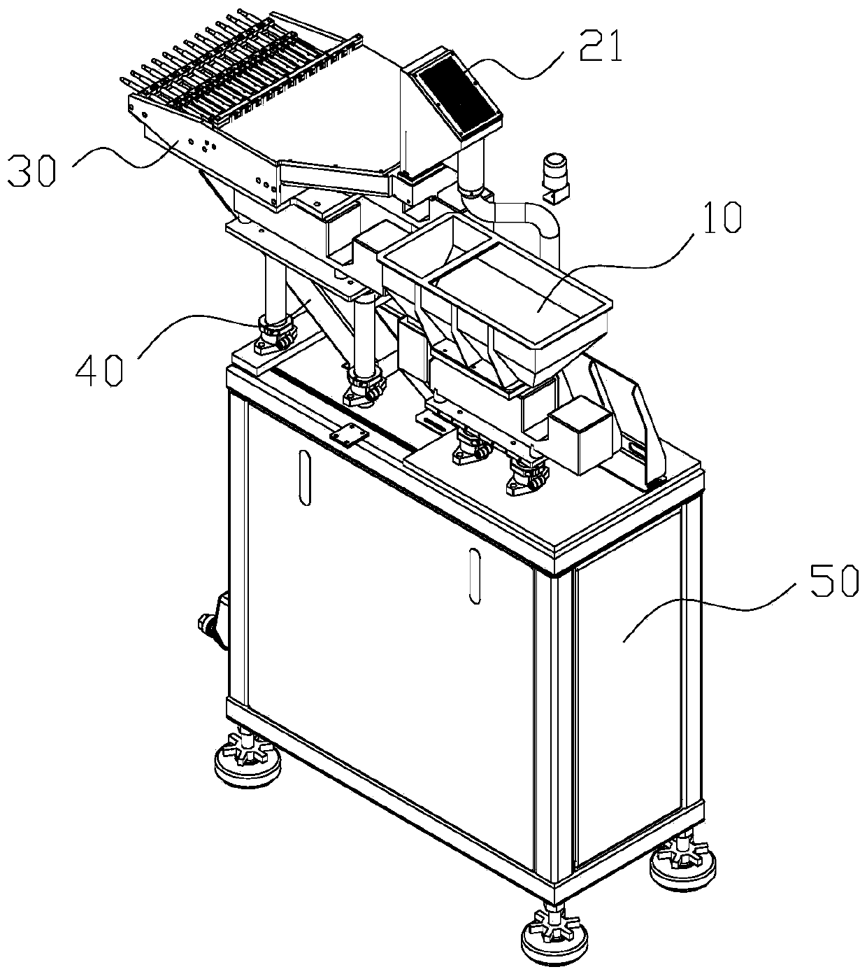
[0025] Such as figure 1 and figure 2 As shown, the embodiment of the present invention provides a separation device, which is used for separating and conveying materials. Specifically, the materials in this embodiment are partially wound or bonded, and the separating device in this embodiment can separate the wound and bonded materials, so that the wound or bonded materials can be separated or dispersed into separate material. The separation device in this embodiment includes a feeding part 10, a material distributing part 20 and a drive mechanism, wherein the material distributing part 20 is connected with the feeding part 10, and the feeding part 10 is used to provide materials to the mat...


PUM


Abstract

The invention provides a separation device and a separation method. The separation device is used for separating and conveying materials; the separation device comprises a feeding part, a material distribution part and a driving mechanism, wherein the material distribution part is connected with the feeding part, and the feeding part is used for providing the materials to the material distribution part, so that the materials can be separated through the material distribution part; the material distribution part comprises a material distribution shell, and a material distribution cavity is defined by the material distribution shell; the driving mechanism is connected with the feeding part, and the driving mechanism is used for blowing high-pressure gas to the feeding part, so that materials in the feeding part can be blown into the material distributing cavity and are separated; and the material distribution part further comprises a material distribution plate, the material distribution plate is arranged on the material distribution shell and is positioned in the material distribution cavity, so that the materials blown into the material distribution cavity by the driving mechanism are subjected to impact separation with the material distribution plate. According to the separation device and the separation method, the technical problem that the separation efficiency of the separation device in the prior art is low can be solved.

Description

technical field [0001] The invention relates to the technical field of material separation equipment, in particular to a separation device and a separation method. Background technique [0002] At present, due to the situation that the springs will be wound in pairs, it will bring greater difficulties to the automatic feeding of the springs. The spring feeding methods in the prior art generally include jet hopper feeding and turntable vibration feeding, wherein jet feeding generally uses high-pressure gas injection to separate the springs, and turntable vibration makes feeding generally through vibration. The coiled springs are separated. [0003] However, the spring separation efficiency of the above two spring feeding methods is low, which is not conducive to the sufficient separation of the springs. Contents of the invention [0004] The main purpose of the present invention is to provide a separation device and a separation method to solve the technical problem of lo...

Claims


Application Information

Patent Timeline
Patent Type & Authority Applications(China)
IPC IPC(8): B65G47/88B65G47/74
CPCB65G47/88B65G47/74
Inventor 刘木林王杰甘凝鼎章途林郑建盛吴挺挺
Owner MAIDER MEDICAL IND EQUIP
Why Eureka
Try Eureka