
Light guide plate single-side automatic film tearing machine and operation process

A light guide plate, automatic technology, applied in the direction of lamination auxiliary operation, packaging, lamination, etc., can solve the problems of large manual workload, pollution of light guide plate, hand acid, etc., to reduce workload, reduce energy consumption, reduce effect of cost

Inactive Publication Date: 2019-09-17
SUZHOU QINGJIANG PRECISION MACHINE TECH
View PDF5 Cites 3 Cited by
  • Summary
  • Abstract
  • Description
  • Claims
  • Application Information

AI Technical Summary

Problems solved by technology

[0004] The purpose of the present invention is to provide an automatic film tearing machine for one side of the light guide plate and its operation process. Through the cooperation between the film tearing arm and the desktop platform, the film tearing operation of the light guide plate can be automatically torn off, which can save labor costs. The advantages of reducing costs and avoiding the loss of scrap caused by personnel pollution to the light guide plate solve the problem that the traditional film removal method is to tear off the protective film on each light guide plate to be produced by the staff with fingers, but this film removal method has There are two problems. One is that the staff often suffer from sore hands and fatigue. The manual workload is relatively large. The other is that there will be some pollutants on the hands of the staff that will indirectly pollute the light guide plate and cause defective products.

Method used


Image

  • Light guide plate single-side automatic film tearing machine and operation process
  • Light guide plate single-side automatic film tearing machine and operation process
  • Light guide plate single-side automatic film tearing machine and operation process

Examples


Embodiment Construction

[0043] In order to make the object, technical solution and advantages of the present invention clearer, the present invention will be further described in detail below in conjunction with the accompanying drawings and embodiments. It should be understood that the specific embodiments described here are only used to explain the present invention, not to limit the present invention.

[0044] The implementation of the present invention will be described in detail below in conjunction with specific embodiments.

[0045] In the drawings of this embodiment, the same or similar symbols correspond to the same or similar components; The indicated orientation or positional relationship is based on the orientation or positional relationship shown in the drawings, and is only for the convenience of describing the present invention and simplifying the description, rather than indicating or implying that the referred device or element must have a specific orientation, or in a specific orien...


PUM


Abstract

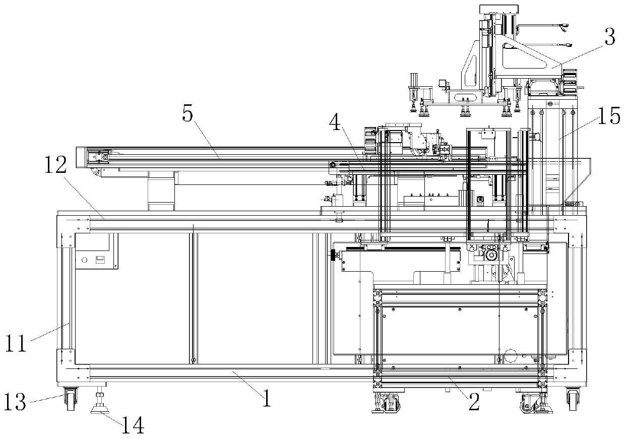
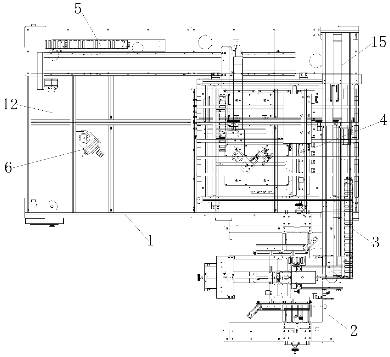
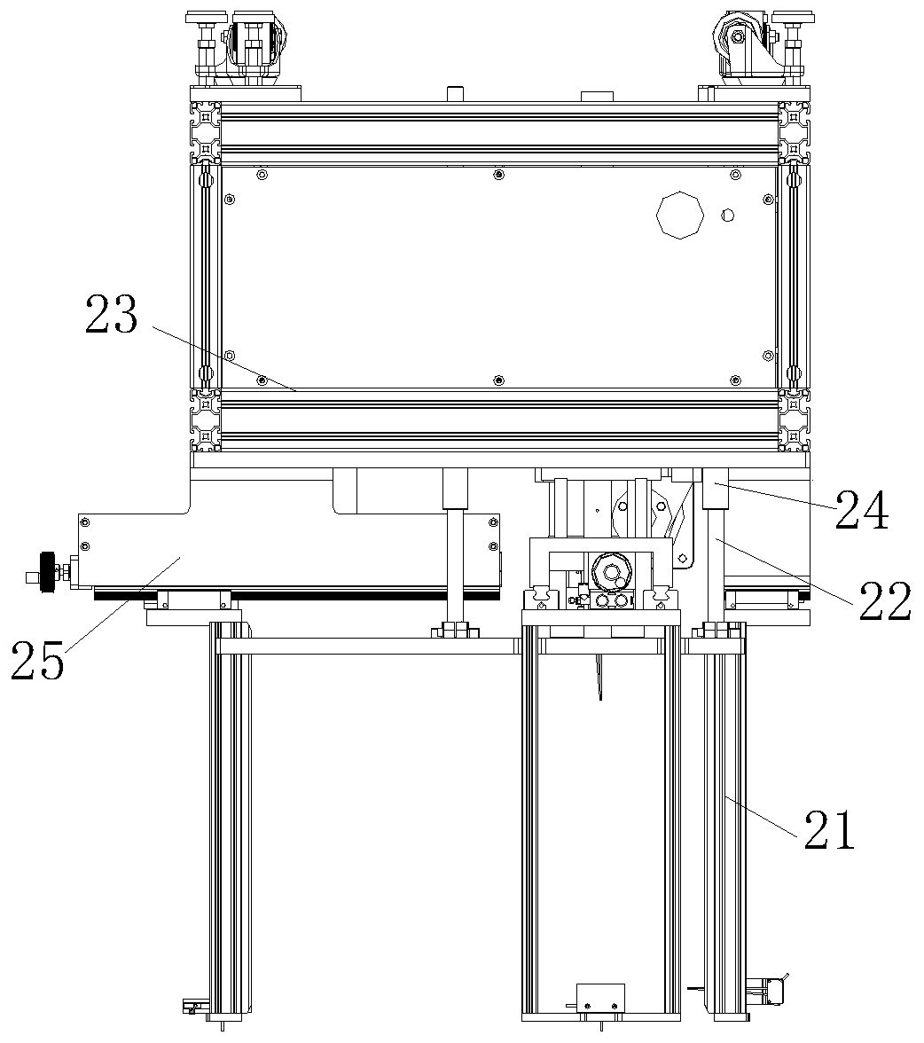
The invention discloses a light guide plate single-side automatic film tearing machine and an operation process. The film tearing machine comprises a rack unit, a tabletop platform is arranged on one side of the top end of the rack unit, a material taking arm is arranged at the top end of one side of the tabletop platform, the material taking arm is connected with a feeding mechanism located on the outer side of the rack unit, a film tearing arm is arranged on one side, away from the feeding mechanism, of the tabletop platform, and the bottom end of the film tearing arm is fixed on the rack unit; the rack unit comprises a mounting frame, a top board is arranged at the top end of the mounting rack, the tabletop platform is fixed on the top board, a support is fixed on one side of the top board, and the material taking arm is arranged on the upper part of the support. According to the film tearing machine and the operation process, the film tearing operation on the light guide plate is automatically realized through the cooperation between the film tearing arm and the tabletop platform, the labor cost can be saved, the labor can be replaced with robots to reduced cost, and the scrapping loss due to workers pollute the light guide plate can be avoided.

Description

technical field [0001] The invention relates to the technical field of light guide plate production equipment, in particular to an automatic film tearing machine for one side of a light guide plate and its operation process. Background technique [0002] The light guide plate is made of optical-grade acrylic / PC sheet, and then high-tech materials with high reflectivity and non-absorbing light are used. Laser engraving, V-shaped cross grid engraving, and UV screen printing technology are used on the bottom surface of the optical-grade acrylic sheet Print the light guide points, and use the optical grade acrylic sheet to absorb the light from the lamp to stay on the surface of the optical grade acrylic sheet. When the light hits each light guide point, the reflected light will spread to all angles, and then destroy the reflection condition by The front side of the light guide plate emits light, and through various light guide points of different densities and sizes, the light ...

Claims


Application Information

Patent Timeline
IPC IPC(8): B65B69/00B32B38/10
CPCB32B38/10B65B69/00
Inventor 杨为新张元方张峰胡悦
Owner SUZHOU QINGJIANG PRECISION MACHINE TECH
Learn More