
Switch laser cutting machine and cutting machining method

A laser cutting machine, laser head technology, applied in laser welding equipment, metal processing equipment, manufacturing tools and other directions, can solve the problems of reducing machine tool durability, machine tool wear, reducing cutting efficiency, etc., to reduce downtime waiting time, The effect of improving operation stability and improving cutting efficiency

Pending Publication Date: 2019-09-17
DONGGUAN GLORYSTAR LASER TECH
View PDF0 Cites 13 Cited by
  • Summary
  • Abstract
  • Description
  • Claims
  • Application Information

AI Technical Summary

Problems solved by technology

[0003] Traditional laser cutting machines generally adopt manual loading and unloading. After completing a cutting process, the operator needs to spend a lot of time on unloading, cleaning and loading, which leads to the downtime of the laser cutting machine in the middle of two cutting processes. Longer, lower cutting efficiency, high waiting cost
[0004] In response to this problem, some merchants have a laser cutting machine, which includes a machine tool, a feeding table, two workbenches and a drag mechanism. Driven to move back and forth between the machine tool and the loading table, but there will be a problem. After the drag mechanism controls the workbench to stop, based on the principle of inertia, the workbench will still have kinetic energy in the horizontal direction, and this kinetic energy is only at this time. It can affect the machine tool and cause impact on the machine tool. In the long run, it will cause wear and tear on the machine tool, reduce the durability of the machine tool, and thus reduce the service life of the laser cutting machine

Method used


Image

  • Switch laser cutting machine and cutting machining method
  • Switch laser cutting machine and cutting machining method
  • Switch laser cutting machine and cutting machining method

Examples


Embodiment Construction

[0032] The structural principle and working principle of the present invention will be further described in detail below in conjunction with the accompanying drawings.

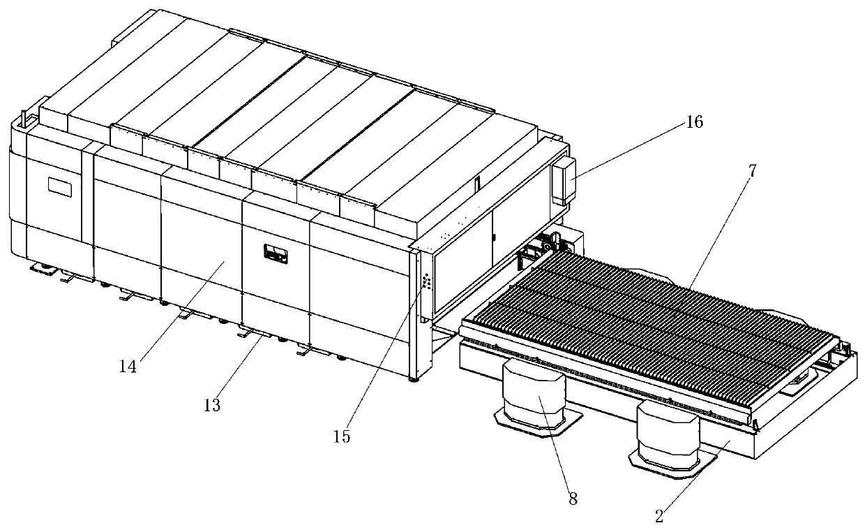
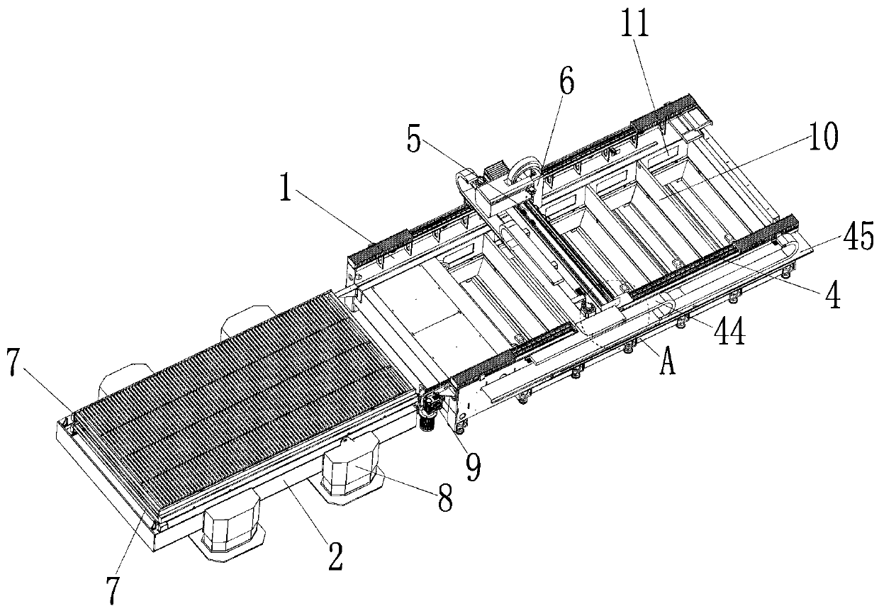
[0033] like Figure 1 ~ Figure 4 As shown, an exchange laser cutting machine includes a machine tool 1, a feeding table 2, a laser head 3, an X-axis drive mechanism 4, a Y-axis drive mechanism 5, a Z-axis drive mechanism 6, a workbench 7, and a drive workbench 7 up and down The moving elevating mechanism 8 and the driving mechanism 9 that drives the workbench 7 to move back and forth between the machine tool 1 and the loading platform 2, the loading platform 2 is arranged at the front end of the machine tool 1, and the X-axis driving mechanism 4 is arranged at On the machine tool 1, the Y-axis driving mechanism 5 is arranged on the X-axis driving mechanism 4, the Y-axis driving mechanism 5 can move back and forth on the X-axis driving mechanism 4, and the Z-axis driving mechanism 6 is arranged on the Y-axis dr...


PUM


Abstract

The invention discloses a switch laser cutting machine which comprises a machine tool, a feeding table, a laser head, an X-axis drive mechanism, a Y-axis drive mechanism, a Z-axis drive mechanism, a workbench, a lifting mechanism and a dragging mechanism. The dragging mechanism comprises a driving roller, a driven roller, a transmission chain and a first drive motor, the driven roller and the driving roller are oppositely arranged in a front-back mode, the transmission chain is wound between the driving roller and the driven roller, the driving roller is in transmission connection with an output shaft of the first driving motor, the transmission chain is provided with two traction wheels, a traction piece is fixedly arranged at the rear end of the workbench, an open groove is formed in the traction piece, the transmission chain drives the workbench to move back and forth between the machine tool and the feeding table through cooperation of the traction wheels and the open groove, when the workbench stops moving, the two traction wheels are located at the front and back ends of the transmission chain, and the axis of the driving roller and the axis of the driven roller are located on the same horizontal plane. The cutting efficiency can be improved, and the service life is prolonged.

Description

technical field [0001] The invention relates to the technical field of metal plate plane cutting equipment, in particular to an exchange laser cutting machine and a cutting processing method. Background technique [0002] The laser cutting machine replaces the traditional mechanical knife with an invisible beam. It has the characteristics of high precision, fast cutting, not limited to cutting patterns, automatic typesetting to save materials, smooth incision, and low processing cost. It will gradually improve or replace it. Traditional metal cutting process equipment. The mechanical part of the laser head has no contact with the workpiece, and will not scratch the surface of the workpiece during work; the laser cutting speed is fast, the incision is smooth and flat, and generally no subsequent processing is required; the cutting heat-affected zone is small, the deformation of the plate is small, and the kerf is narrow ( 0.1mm~0.3mm); the incision has no mechanical stress, ...

Claims


Application Information

Patent Timeline
Patent Type & Authority Applications(China)
IPC IPC(8): B23K26/38B23K26/70
CPCB23K26/38B23K26/702
Inventor 姚玉东孙加邦尹怀化李荣飞刘展鹏蔡永帮刘南麟刘小冬
Owner DONGGUAN GLORYSTAR LASER TECH
Learn More