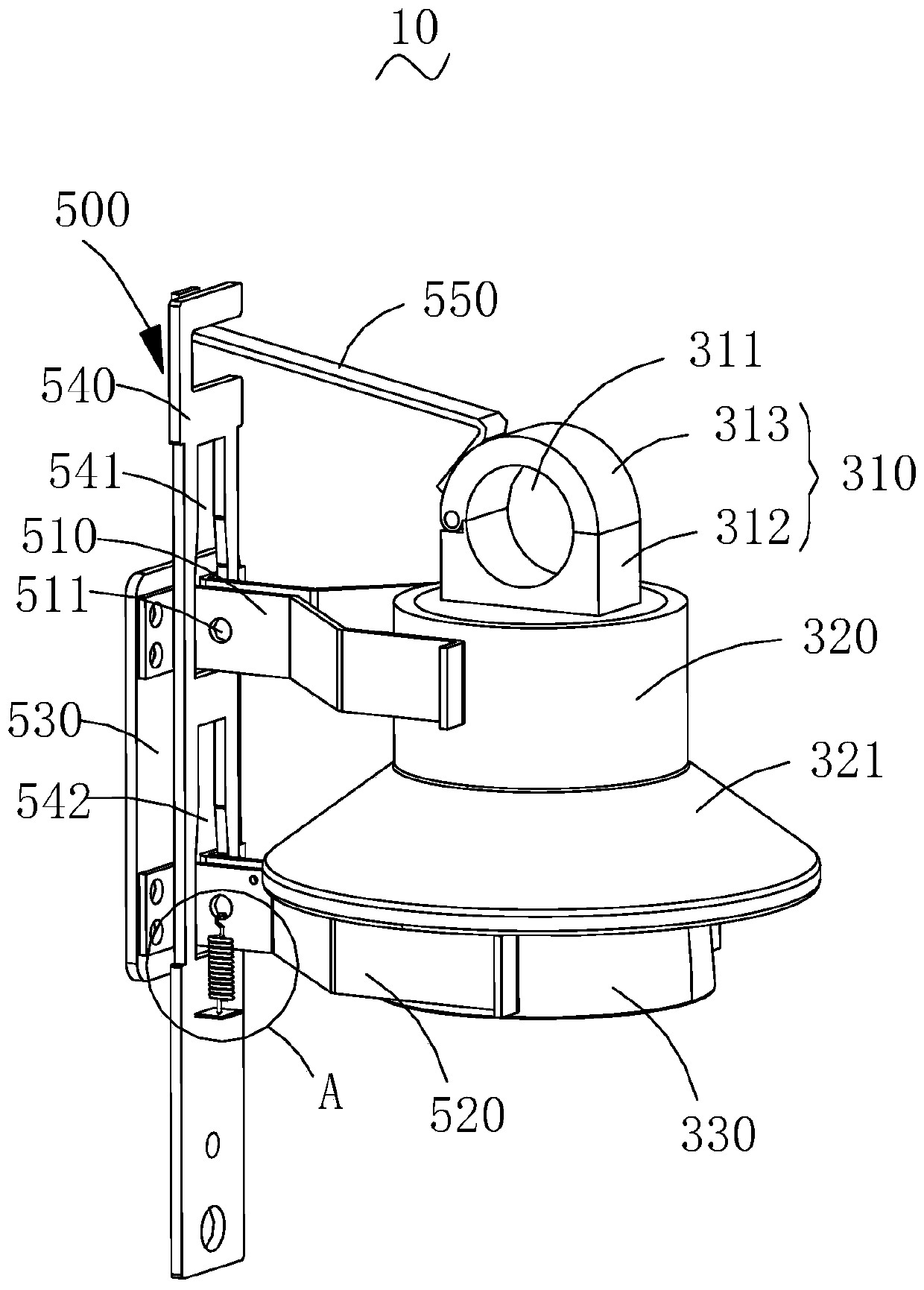
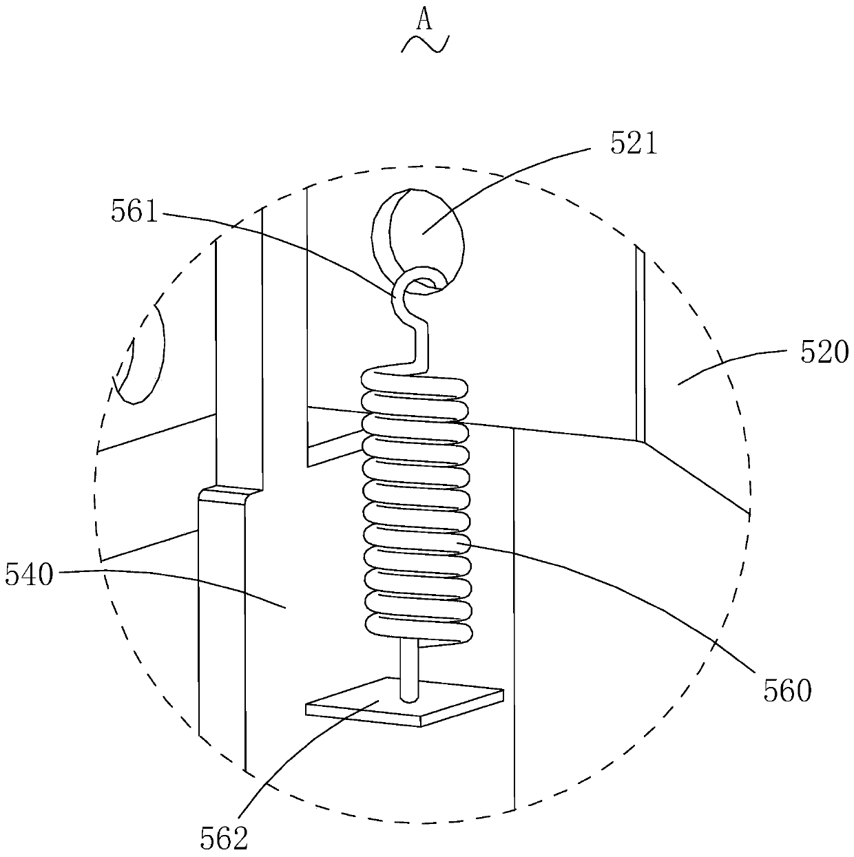
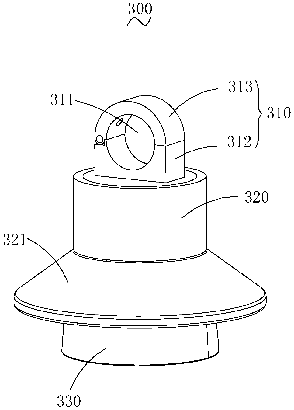
Overhead line electricity testing device

An electroscope device and overhead line technology, applied in the direction of fault location, indicating the existence of current/voltage, and detecting faults according to conductor types, etc., can solve problems such as insufficient separation of contacts, inability to sense current, and arcing, so as to avoid Personal and equipment injury, improve detection safety, avoid insulation failure effects

Pending Publication Date: 2019-09-13
GUANGZHOU POWER SUPPLY BUREAU GUANGDONG POWER GRID CO LTD
View PDF0 Cites 4 Cited by
  • Summary
  • Abstract
  • Description
  • Claims
  • Application Information

AI Technical Summary

Problems solved by technology

However, after the switch is disconnected, it is impossible to judge whether the switch can be opened through the electric test (under this working condition, both ends of the switch are charged), and the status indication pointer of the switch on the column can only be used to judge whether the switch has been opened, and then pull the switch. Operation of the knife gate
However, the opening and closing state indication of the switch on the column depends on the internal mechanical transmission. Aging, corrosion, looseness, or unclear indications caused by various reasons may lead to misjudgment of the switch state, for example, there is a fault inside the switch , after the opening operation, the indication is in the opening state, but the switch does not actually act, or the contacts are not sufficiently separated after the action, and the switch is still in the conduction state in essence
At this time, the operation of the knife switch will cause an accident of pulling the knife switch with load, causing an arc, and there is a considerable hidden danger to personal and equipment safety.
The knife switch cannot be operated with load current. The existing electroscope is a voltage-type electroscope, which can only test whether there is voltage on the overhead line, but cannot sense whether there is current, and cannot meet the electrical inspection requirements of the above occasions.

Method used


Image

  • Overhead line electricity testing device
  • Overhead line electricity testing device
  • Overhead line electricity testing device

Examples


Embodiment Construction

[0027] In order to facilitate the understanding of the present invention, the present invention will be described more fully below with reference to the associated drawings. Preferred embodiments of the invention are shown in the accompanying drawings. However, the present invention can be embodied in many different forms and is not limited to the embodiments described herein. On the contrary, the purpose of providing these embodiments is to make the disclosure of the present invention more thorough and comprehensive.

[0028] It should be noted that when an element is referred to as being “disposed on” another element, it may be directly on the other element or there may also be an intervening element. When an element is referred to as being "connected to" another element, it can be directly connected to the other element or intervening elements may also be present. The terms "vertical," "horizontal," "left," "right," and similar expressions are used herein for purposes of ...


PUM


Abstract

The invention relates to an overhead line electricity testing device, comprising a shell and an electricity testing module, wherein the shell comprises an induction lantern ring and a mounting seat, the induction lantern ring is arranged at one end of the mounting seat, the induction lantern ring is provided with an accommodating through hole for accommodating an overhead line, a first accommodating space is opened in the induction lantern ring, and a second accommodating space is opened in the mounting seat; and the electricity testing module comprises a coil, a common mode inductor, a voltage stabilizing unit, a rectifying unit and a lamp panel, the coil is arranged in the first accommodating space, the common mode inductor, the voltage stabilizing unit and the rectifying unit are arranged in the second accommodating space, and the lamp panel is arranged at one end of the mounting seat away from the induction lantern ring. The overhead line electricity testing device senses overheadline current into a secondary circuit, can accurately judge whether current flows through the overhead line, requires no external power supply, avoids an insulation fault of the overhead line and thesecondary circuit, and can avoid causing personal injury and equipment damage. Furthermore, the shell is used for protecting the electricity testing module, so that the service life of the overhead line electricity testing device is effectively prolonged.

Description

technical field [0001] The invention relates to the technical field of electric equipment, in particular to an electrical inspection device for overhead lines. Background technique [0002] Usually, in order to improve the reliability of power supply and reduce the number of households during power outages, in principle, all those who can switch to power supply must be switched to power supply when the distribution network is undergoing maintenance work. For overhead lines, many feeders use pole-mounted switches as tie switches. After the maintenance work is completed and the original power supply mode is restored, it is generally necessary to switch on the connecting column to unlink the feeders. When operating on site, first turn off the switch, and then open the knife gates on both sides of the switch. However, after the switch is disconnected, it is impossible to judge whether the switch can be opened through the electric test (under this working condition, both ends o...

Claims


Application Information

Patent Timeline
Patent Type & Authority Applications(China)
IPC IPC(8): G01R31/08G01R19/15
CPCG01R31/085G01R19/15
Inventor 温伟弘黎洪光陈文炜郑欣姜明凯彭灵利周仕杰吕泉成高军伟于博文
Owner GUANGZHOU POWER SUPPLY BUREAU GUANGDONG POWER GRID CO LTD
Why Eureka
Try Eureka