
Automatic dust removing apparatus for construction sites

A technology for dust removal equipment and construction sites, which is applied in chemical instruments and methods, separation of dispersed particles, filtration of dispersed particles, etc. It can solve problems such as unfavorable health of construction workers and surrounding residents, low degree of automation of dust removal equipment, and poor dust removal effect. , to achieve the effect of protecting normal work, improving the effect of dust treatment, and improving the effect of absorbing dust

Inactive Publication Date: 2019-09-13
肥西县碧涛建材有限公司
View PDF2 Cites 0 Cited by
  • Summary
  • Abstract
  • Description
  • Claims
  • Application Information

AI Technical Summary

Problems solved by technology

[0002] With the continuous development of society, the construction industry has developed rapidly. The construction site is a place where construction projects are being developed and civil engineering is being carried out. The entry and exit of vehicles and construction sites is a very common phenomenon. If the vehicle-mounted dregs and construction waste leave the site, if the necessary treatment is not carried out, a large amount of dust pollution will inevitably be generated, which is not conducive to the health of construction workers and surrounding residents. Especially the secondary construction and decoration of the indoor structure, the environment is closed, and the indoor workers will inhale a lot of dust when they are working, which will cause great damage to the health of the workers in the long run
[0003] The existing dust removal equipment has a low degree of automation and low dust removal efficiency, and further improvement is needed to improve the effect of dust removal and automation
[0004] Chinese patent literature (publication number: CN107519719A) discloses a kind of dedusting equipment for construction sites, including induced draft fan, atomizing nozzle, rotating water spray pipe, water tank, base, water pump, motor, dust removal tank and air volume regulating valve, said introduction The fan is fixedly installed on the base through the mounting frame, the front end of the induced draft fan is fixedly installed with an air inlet, and the dust removal tank is fixedly installed on the base through a bracket. Arranged in letters, the air outlets with filters are fixedly installed at the two sides of the top of the dust removal tank, the motor is fixed at the bottom of the dust removal tank, and the rotating water spray pipe is connected to the motor through a coupling. The degree of automation of this dust removal equipment is low. Manual operation is required, time-consuming and labor-intensive, and further improvement is still needed
[0005] Chinese patent document (publication number: CN108968821A) discloses an automatic construction site dust removal equipment, which belongs to the field of environmental protection equipment, including a base, a fixed rod and a spray plate, a fixed rod is set in the middle of the base; a water storage tank is set in the right part of the base; A water injection valve is set outside the tank; a cross bar is set on the upper part of the water storage tank; a water pump is set on the cross bar; the water pump is connected to the suction pipe; a water pipe is set on the water pump; a spray plate is set on the water pipe; Set the dust bucket; set the dust tube between the dust bucket and the dust collection box; set the connecting pipe on the dust bucket; set the suction pump on the connecting pipe; set the curved dust collection pipe on the suction pump; set the universal wheel under the base, Although the dust removal equipment can be automated, it is used in the construction field, the dust removal effect is not very good, and the dust removal efficiency is relatively low

Method used


Image

  • Automatic dust removing apparatus for construction sites
  • Automatic dust removing apparatus for construction sites
  • Automatic dust removing apparatus for construction sites

Examples


Embodiment Construction

[0032] The technical solution in the invention will be clearly and completely described below in conjunction with the accompanying drawings and specific embodiments. Apparently, the described embodiments are only a part of the embodiments of the present invention, not all of them. Based on the embodiments of the present invention, all other embodiments obtained by persons of ordinary skill in the art without making creative efforts belong to the protection scope of the present invention.

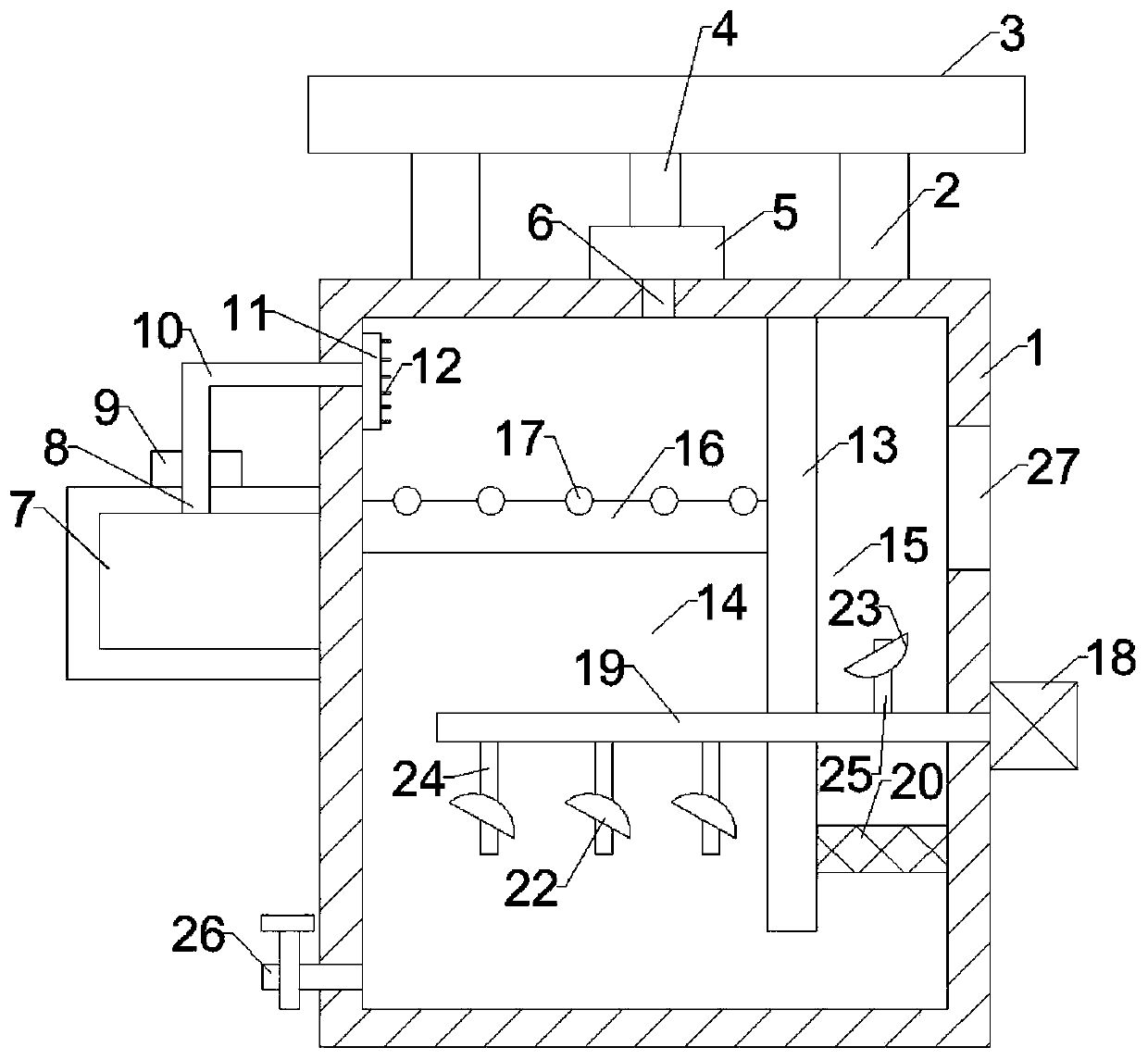
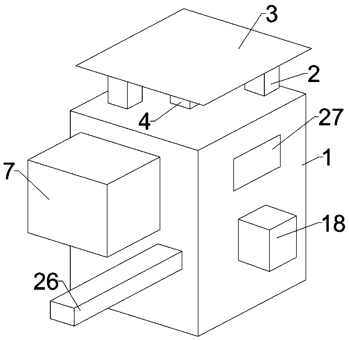
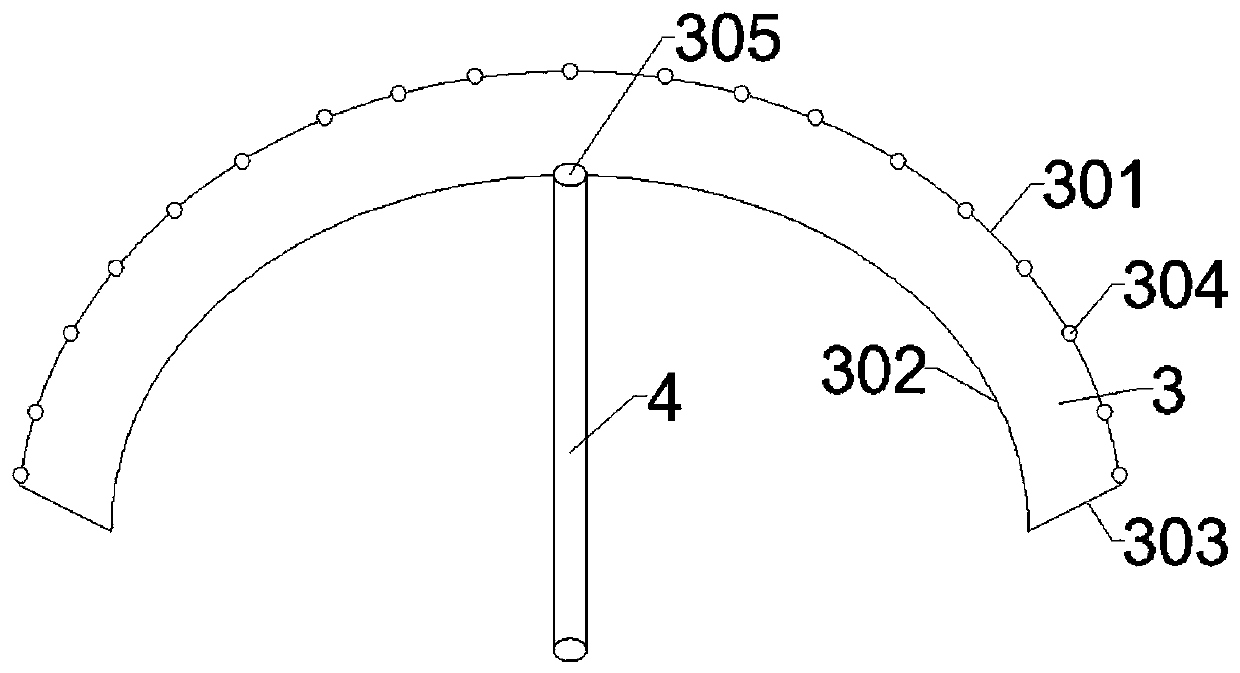
[0033] Such as Figure 1-4 As shown, a construction site automatic dust removal equipment of the present invention includes a dust removal box 1, the upper part of the dust removal box 1 is connected with an integrated cover 3 through a support frame 2, and the dust collection cover 3 is a first dust collection plate 301, a second Two dust collecting plates 302 and combined plate 303 constitute, the first dust collecting plate 301, the second dust collecting plate 302 have the same size and ...


PUM


Abstract

The invention relates to an automatic dust removing apparatus for construction sites. The automatic dust removing apparatus comprises a dust removing box body. The upper part of the dust removing boxbody is connected with a dust collecting cover through a support frame; the dust collecting cover is composed of a first dust collecting plate, a second dust collecting plate and a combined plate; thefirst dust collecting plate and the second dust collecting plate have the same size and the same shape and are both of an arc-shaped structure; dust collecting holes are uniformly formed in the upperpart of the first dust collecting plate; a dust discharging port is formed in the second dust collecting plate; and a dust collecting tube is arranged on the second dust collecting plate at a position where the dust discharging port is located. The first dust collecting plate of the invention is of the arc-shaped structure, and the dust collecting holes are uniformly formed in the first dust collecting plate, so dust can be absorbed from different directions and a dust absorption area is increased; and a primary treatment net can realize primary dust treatment measures, improve dust treatmenteffect and protect the normal operation of a blower.

Description

technical field [0001] The invention relates to the technical field of dust removal, in particular to automatic dust removal equipment for construction sites. Background technique [0002] With the continuous development of society, the construction industry has developed rapidly. The construction site is a place where construction projects are being developed and civil engineering is being carried out. The entry and exit of vehicles and construction sites is a very common phenomenon. If the vehicle-mounted dregs and construction waste leave the site, if the necessary treatment is not carried out, a large amount of dust pollution will inevitably be generated, which is not conducive to the health of construction workers and surrounding residents. Especially in the secondary construction and decoration of indoor structures, the environment is closed, and indoor workers will inhale a large amount of dust when they are working, which will cause great damage to the health of work...

Claims


Application Information

Patent Timeline
IPC IPC(8): B01D50/00B01D46/54B01D46/00B01D46/10
CPCB01D46/0036B01D46/10B01D46/543B01D50/00
Inventor 李绍敏罗彪陈思刚李先武
Owner 肥西县碧涛建材有限公司
Learn More