
Quad-rotor unmanned aerial vehicle visual target tracking method based on binocular camera

A quad-rotor drone and binocular camera technology is applied in the field of visual target tracking of quad-rotor drones based on binocular cameras, which can solve the problem of poor tracking ability, affect the practicability of visual target tracking drones, and do not have long-term performance. Tracking ability and other issues, to achieve the effect of high precision, fast calculation speed and small delay

Active Publication Date: 2019-09-10
UNIV OF ELECTRONICS SCI & TECH OF CHINA
View PDF11 Cites 29 Cited by
  • Summary
  • Abstract
  • Description
  • Claims
  • Application Information

AI Technical Summary

Problems solved by technology

[0003] There are two main implementation methods for existing similar UAV target tracking systems. The first method requires the tracking target to carry GPS or other electronic beacons that can communicate with the UAV. The UAV completes the target tracking by receiving the positioning information of the beacon. This method obviously has great limitations in application; the second method is to use the visual tracking algorithm to track the tracking target, but most of the tracking algorithms used are traditional tracking algorithms, which have poor tracking ability and do not have Long-term tracking capability. In addition, many similar systems need to know the shape and size of the target in advance in order to obtain the state information such as the relative distance between the UAV and the tracking target and the speed of movement, or use the flying height of the UAV as one of the state estimation conditions. one, this makes it only possible to track known targets or targets that are moving on the ground
These situations affect the practicability of visual target tracking drones, and the application scenarios have great limitations

Method used


Image

  • Quad-rotor unmanned aerial vehicle visual target tracking method based on binocular camera
  • Quad-rotor unmanned aerial vehicle visual target tracking method based on binocular camera
  • Quad-rotor unmanned aerial vehicle visual target tracking method based on binocular camera

Examples


Embodiment

[0043] For the convenience of description, the relevant technical terms appearing in the specific implementation are explained first:

[0044] Offboard: external mode;

[0045] Tiny-Yolov3: Real-time target detection algorithm;

[0046] APCE (Average Peak-to Correlation Energy): a tracking quality judgment indicator;

[0047] SVM (Support Vector Machine): a nonlinear classifier algorithm based on supervised learning;

[0048] ORB (Oriebted Fast and Rotated BRIEF): an algorithm for fast feature point extraction and description;

[0049] EKF (Extended Kalman Filter): Kalman filter algorithm;

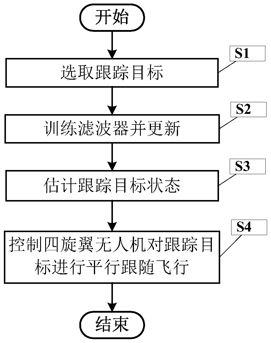
[0050] figure 1 It is a flow chart of the quadrotor UAV visual target tracking method based on the binocular camera of the present invention.

[0051] In this example, if figure 1 Shown, a kind of quadrotor unmanned aerial vehicle visual target tracking method based on binocular camera of the present invention comprises the following steps:

[0052] S1. Select the tracking target

...


PUM


Abstract

The invention discloses a quad-rotor unmanned aerial vehicle visual target tracking method based on a binocular camera. The method comprises the following steps of detecting a tracking target througha target recognition algorithm, finishing the position tracking and scale tracking of the target in pixel significance by using a visual tracking algorithm based on correlation filtering, and judgingwhether a repositioning program needs to be started or a long-term tracker needs to be updated according to a tracking effect; secondly, according to an image area selected by the tracking frame, calculating the relative distance between the quad-rotor unmanned aerial vehicle and the tracking target by using an LK optical flow method, and after coordinate conversion, realizing the global state estimation of the tracking target by using a Kalman filter; and finally, according to the estimated global position and speed state of the target, designing the state quantity of an outer loop control system of the unmanned aerial vehicle to realize the delay-free stable tracking of the tracked target by the unmanned aerial vehicle.

Description

technical field [0001] The invention belongs to the technical field of quadrotor drones, and more specifically relates to a binocular camera-based visual target tracking method for quadrotor drones. Background technique [0002] In the field of quadrotor UAV technology, visual target tracking UAV has good practical value. In the field of military reconnaissance, through the use of target recognition and tracking technology on UAVs, the target can be continuously locked and monitored, and the position and movement state information of the target can be estimated, so as to guide one's own side to carry out precise fire strikes; in terms of aerial photography, small to consumption In the high-end market, ordinary consumers have a huge demand for follow-up shots when playing games, and in the industrial application market, motion close-up shots during film and television shooting. These functions used to require experienced drone operators to complete, and the operating threshol...

Claims


Application Information

Patent Timeline
IPC IPC(8): G06K9/00G06K9/46G06K9/62G05D1/12
CPCG05D1/12G06V20/64G06V10/40G06V2201/07G06F18/214
Inventor 李瑞刘奇胜史莹晶吴士成
Owner UNIV OF ELECTRONICS SCI & TECH OF CHINA
Learn More