Lens and laser projection device

A technology of laser projection and light bar, which is applied in the direction of lens, projection device, optics, etc., can solve the problem of low effective receiving efficiency of optical path

Pending Publication Date: 2019-09-10
QINGDAO HISENSE LASER DISPLAY CO LTD
View PDF0 Cites 4 Cited by
  • Summary
  • Abstract
  • Description
  • Claims
  • Application Information

AI Technical Summary

Problems solved by technology

[0006] In order to solve the problem that a part of the area of ​​the circular spot in the direction of the short side of the light rod fails to enter the light rod during the beam shrinkage process of the excitation light, resulting in a decrease in the effective receiving efficiency of the light path, the present invention provides a diffuser and a laser projection device

Method used


Image

  • Lens and laser projection device
  • Lens and laser projection device
  • Lens and laser projection device

Examples


Embodiment Construction

[0033] The following will clearly and completely describe the technical solutions in the embodiments of the present invention with reference to the accompanying drawings in the embodiments of the present invention. Obviously, the described embodiments are only some, not all, embodiments of the present invention. Based on the embodiments of the present invention, all other embodiments obtained by persons of ordinary skill in the art without making creative efforts belong to the protection scope of the present invention.

[0034] In the description of the present invention, unless otherwise specified, "plurality" means two or more.

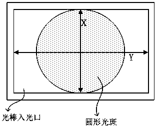
[0035] An embodiment of the present invention provides a diffusion sheet, which is applied to a laser projection device, figure 2 It is a top view of the microstructure in the diffusion sheet of the embodiment of the present invention, such as figure 2 As shown, the diffusion sheet includes N microstructures for diffusing the incident circular li...


PUM


Abstract

The invention relates to a diffuser applied to a laser projection device. The diffuser includes N microstructures for diffusing incident circular light beams, and N is a positive integer greater thanor equal to 10. Each of the N microstructures has first and second sections perpendicular to each other, and the diffusion angle of the second section is larger than that of the first section. When the diffuser in the embodiment of the invention is applied to a laser projection device, the original circular excitation spots can be changed into elliptical spots. On one hand, the excitation spot area of fluorescent powder is increased, the power density of excitation light is reduced, and higher excitation light power can be withstood. On the other hand, the unused area of light bars can be utilized to increase the fluorescence absorption of the light path.

Description

technical field [0001] The invention relates to the technical field of laser display, in particular to a diffusion sheet and a laser projection device. Background technique [0002] In related technologies, the excitation light spot irradiated on the phosphor is generally circular, and the excited fluorescent spot is also circular. on chip. In order to be consistent with the size ratio of the optical chip, the cross section of the light rod is generally rectangular, so its light entrance is also rectangular. figure 1 It is a schematic diagram of the circular light spot entering the light rod light entrance in the prior art related to the present invention, such as figure 1 As shown, if the circular spot shines on the light rod through the rectangular light entrance, there will be no light entering in part of the area along the long side of the light rod, causing part of the etendue to be wasted, and the maximum threshold of the luminous flux output by the light rod will al...

Claims


Application Information

Patent Timeline
IPC IPC(8): G03B21/20G02B5/02G02B3/00
CPCG02B3/00G02B5/021G02B5/0278G03B21/204G03B21/208
Inventor 王强刘显荣
Owner QINGDAO HISENSE LASER DISPLAY CO LTD
Why Eureka
Try Eureka