Distributed low-current ground wire selection method and wire selection system thereof
A technology of small current grounding and line selection method, applied in the direction of measuring electricity, measuring electrical variables, measuring devices, etc., can solve the problem of no distributed small current grounding line selection method, inconvenient maintenance and management of grounding protection devices, and difficult arrangements, etc. To achieve the effect of convenient layout and space location arrangement, reliable judgment results, and convenient device maintenance and management
- Summary
- Abstract
- Description
- Claims
- Application Information
AI Technical Summary
Problems solved by technology
Method used
Image
Examples
Embodiment 1
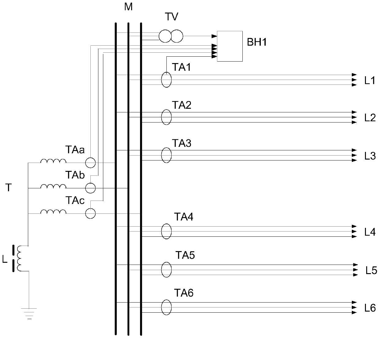
[0036] A typical implementation, such as figure 1 The distributed small current grounding line selection system shown. The power supply sends power to the transformer T, the transformer T sends power to the bus M, and the neutral point of the transformer T is grounded through the arc suppression coil L. Suppose the bus M is connected with N power supply lines, N=6. The six lines are L1, L2, L3, L4, L5, and L6. Each line has its own ground protection device BH1, BH2, BH3, BH4, BH5, BH6, for the convenience of drawing, figure 1 Only draw BH1. The zero-mode current i of the current transformers TA1, TA2, TA3, TA4, TA5, and TA6 of the 6 power supply lines 0,i (i=1, 2, 3, 4, 5, 6) respectively input the grounding protection devices BH1, BH2, BH3, BH4, BH5, BH6 of each line, zero-mode current i 0,i The reference direction is consistent with the convention that the busbar points to the line. i 0,i represents an instantaneous value, Represents a phasor. As we all know, the po...
Embodiment 2
[0056] Such as figure 1 In the distribution network shown, the A, B, and C phases of the transformer T have current transformers TAa, TAb, and TAc respectively. The current transformers TAa, TAb, and TAc respectively reflect the primary side current i a,T i b,T i c,T . However, the A and C phases of the transformer T in some distribution networks have current transformers respectively, and the B phase does not have a current transformer.
[0057] Field actual operation experience shows that when a ground fault occurs in a small current grounding system, the attenuated DC component of the neutral point arc suppression coil of the transformer is very small, and ignoring it has little effect on the line selection criterion for small current grounding. Therefore, when phase B is the faulty phase, let transformer T faulty phase remove power frequency and high frequency residual current i g,T,α =-(i a,T,α + i c,T,α ), still can use the disclosed method to select the fault lin...
Embodiment 3
[0059] Such as figure 1 In the distribution network shown, the A, B, and C phases of the transformer T have current transformers TAa, TAb, and TAc respectively. The current transformers TAa, TAb, and TAc respectively reflect the primary side current i a,T i b,T i c,T . In order to further reduce the lead-in wires of the ground protection device, the ground protection device can only take one-phase current, for example, take A-phase current.
[0060] It is not difficult to analyze, when phase B is the fault phase, the power frequency and high frequency residual current i of transformer T fault phase g,T,α =-2i a,T,α , to perform calculations, the fault line can still be selected with the disclosed method. When phase C is the fault phase, let transformer T fault phase remove power frequency and high frequency residual current i g,T,α =-2i a,T,α , to perform calculations, the fault line can still be selected with the disclosed method. However, the sensitivity and reliabi...
PUM
 Abstract
Description
Claims
Application Information
 - R&D
- Intellectual Property
- Life Sciences
- Materials
- Tech Scout
- Unparalleled Data Quality
- Higher Quality Content
- 60% Fewer Hallucinations
Browse by: Latest US Patents, China's latest patents, Technical Efficacy Thesaurus, Application Domain, Technology Topic, Popular Technical Reports.
© 2025 PatSnap. All rights reserved.Legal|Privacy policy|Modern Slavery Act Transparency Statement|Sitemap|About US| Contact US: help@patsnap.com


