


Quick Research
Generate reliable direction feasibility study reports for your R&D in just a few steps.

Technical Q&A
Discover and master advanced knowledge NOW. Basics, ideas, possibilities, all at once.

Find Solutions
As an expert in R&D theories, this can generate solutions to your technical problems instantly.

Evaluate Feasibility
Analyze your overall solution with one click, know your potential R&D risks in advance.

Monitor Landscape
Get weekly tech updates, stay abreast of the latest tech innovations and key insights.
Ventilation system of fuel tank
A ventilation system and fuel tank technology, applied in the direction of valves for ventilation, arrangement combined with internal combustion engine fuel supply, containers, etc., can solve problems such as limiting the freedom of ventilation fixed openings, restricting product development, increasing design difficulty, etc., to achieve The design requirements are simplified, the composition structure is simple, and the effect of increasing the degree of design freedom
- Summary
- Abstract
- Description
- Claims
- Application Information
AI Technical Summary
Problems solved by technology
Method used
Image

Examples
Embodiment 1
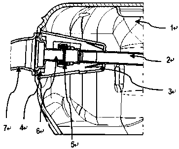
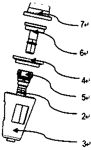
[0022] Embodiment 1: see Figure 1-Figure 6 , a fuel tank ventilation system, the ventilation system includes at least one fuel tank fixed interface structure 4 for ventilation fixed on the wall of the fuel tank, a quick-fit female joint 5 and an external male joint 6, the quick-fit female joint 5 is connected to the ventilation pipeline 2 inside the fuel tank 1 and plugged and fixed with the external male joint 6 welded or assembled on the fuel tank 1; the quick-fit female joint 5 is fixed on the inner wall of the fuel tank 1 through the protective cover 3; The welding piece 7 is welded to the fixed interface structure 4 of the fuel tank on the outer wall of the fuel tank to realize the sealing of the entire ventilation system. The protective cover 3 is composed of a welding pit structure at the cover body and the end, and the pits are arranged at end of the cover. The welding surface of the protection cover 3 of this solution is designed with a pitted structure, which is cl...
Embodiment 2
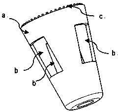
[0023] Example 2: see Figure 1-Figure 6 , as an improvement of the present invention, the cover body a has two openings b to ensure that the fuel is discharged from it in time; the pitted structure c at the end is used for the fuel tank to be welded to it during the blow molding process and to carry out Fixed; at the same time, the ventilation pipeline 2 drawn out from the protective cover 3 has a raised d structure in the tail area of the cover body to prevent the external male connector 6 from being forced out of the protective cover 3 during the assembly process with the quick-connect female connector 5, Such as Figure 4 shown.
Embodiment 3
[0024] Embodiment 3: see Figure 1-Figure 6 , as an improvement of the present invention, the fixed interface structure 4 of the fuel tank is molded during the blow molding process of the fuel tank, and is a concave interface e, and the inner diameter of the fixed interface structure 4 is larger than the outer diameter of the matching joint. The supporting structure is externally connected with male joints 6, and the matching gap tolerance is designed within 0.1 mm. The fixed interface structure 4 of the fuel tank on the fuel tank 1 is formed during the blow molding of the tank body. This structure has a coupling structure that is copied from the external male joint 6. Welding to achieve fixation and sealing. The structure of the externally connected male joint is designed in conjunction with the quick-fit female joint. The outer diameter of the externally connected male joint and the boss f on it cooperate with the inner diameter of the female joint to ensure tightness; the m...
PUM
 Abstract
Description
Claims
Application Information
 - R&D Engineer
- R&D Manager
- IP Professional
- Industry Leading Data Capabilities
- Powerful AI technology
- Patent DNA Extraction
Browse by: Latest US Patents, China's latest patents, Technical Efficacy Thesaurus, Application Domain, Technology Topic, Popular Technical Reports.
© 2024 PatSnap. All rights reserved.Legal|Privacy policy|Modern Slavery Act Transparency Statement|Sitemap|About US| Contact US: help@patsnap.com