High-precision sucker mechanism used for optical fiber cable machining

A suction cup mechanism, fiber optic cable technology, applied in the direction of walking bridge cranes, cranes, load hanging components, etc., can solve the problems of high quality of steel and aluminum strips, reduce damage, reduce labor intensity, and improve feeding efficiency. Effect

Inactive Publication Date: 2019-09-10
JIANGSU HENGTONG PHOTOELECTRIC
View PDF5 Cites 0 Cited by
  • Summary
  • Abstract
  • Description
  • Claims
  • Application Information

AI Technical Summary

Problems solved by technology

[0003] During the processing of communication cables, before covering the resin shell, wrap steel and aluminum strips around the wires to form a protective structure, which can not only protect the wires from damage by pests, but also strengthen the cable structure and increase its service life However, due to the high quality of the rolled steel and aluminum strips, there is an urgent need for a feeding mechanism that can carry the steel and aluminum strips and is convenient for the staff to use.

Method used


Image

  • High-precision sucker mechanism used for optical fiber cable machining
  • High-precision sucker mechanism used for optical fiber cable machining
  • High-precision sucker mechanism used for optical fiber cable machining

Examples


Embodiment 1

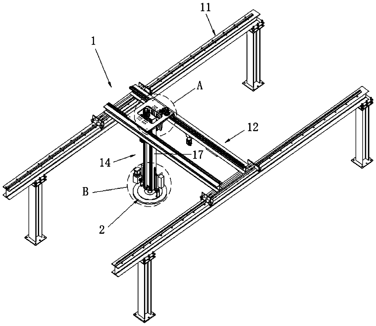
[0032] Embodiment 1: A high-precision sucker mechanism for optical fiber and cable processing, refer to the attached Figure 1-5 , including a suction cup assembly 2 installed on a displacement mechanism 1, the displacement mechanism 1 includes an X-axis assembly 11, a Y-axis assembly 12 and a Z-axis assembly 14, and the Y-axis assembly 12 is movably mounted on the X-axis assembly 11 , the Z-axis assembly 14 is connected to the Y-axis assembly 12 and can move along the Y-axis direction, and the suction cup assembly 2 is mounted on the Z-axis assembly 14 and can move along the Z-axis direction;

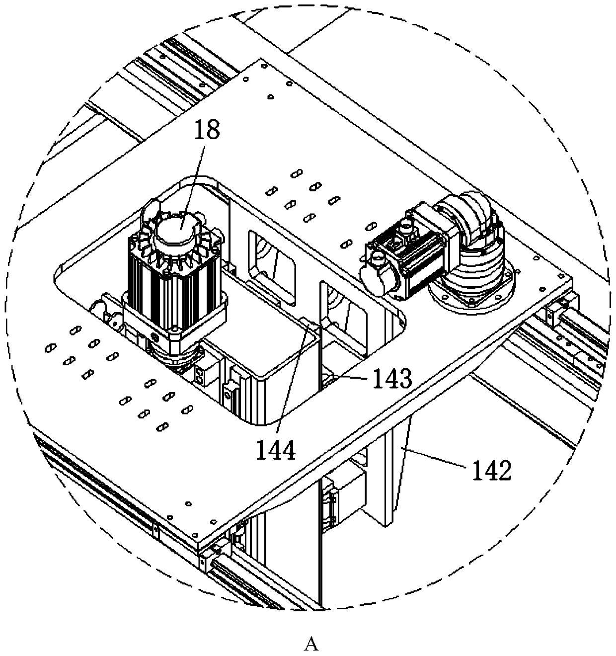
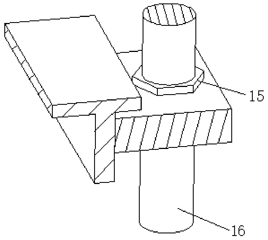
[0033] The Z-axis assembly 14 further includes a drive nut 15, a drive screw 16, a movable column 17 and a Z-axis motor 18. The drive nut 15 is sleeved on the drive screw 16 and is connected to the Y-axis assembly 12. The Z-axis motor 18 is connected with the driving screw rod 16 for driving the driving screw rod 16 to rotate;

[0034]The suction cup assembly 2 includes a vacuum pump ...

Embodiment 2

[0041] Embodiment 2: A high-precision sucker mechanism for optical fiber and cable processing, refer to the attached Figure 1-5 , including a suction cup assembly 2 installed on a displacement mechanism 1, the displacement mechanism 1 includes an X-axis assembly 11, a Y-axis assembly 12 and a Z-axis assembly 14, and the Y-axis assembly 12 is movably mounted on the X-axis assembly 11 , the Z-axis assembly 14 is connected to the Y-axis assembly 12 and can move along the Y-axis direction, and the suction cup assembly 2 is mounted on the Z-axis assembly 14 and can move along the Z-axis direction;

[0042] The Z-axis assembly 14 further includes a drive nut 15, a drive screw 16, a movable column 17 and a Z-axis motor 18. The drive nut 15 is sleeved on the drive screw 16 and is connected to the Y-axis assembly 12. The Z-axis motor 18 is connected with the driving screw rod 16 for driving the driving screw rod 16 to rotate;

[0043] The suction cup assembly 2 includes a vacuum pump...


PUM


Abstract

The invention discloses a high-precision sucker mechanism used for optical fiber cable machining. The high-precision sucker mechanism comprises a sucker assembly installed on a displacement mechanism.The sucker assembly comprises a vacuum pump, a base plate and a sucker installed on the bottom face of the base plate. A sealing ring is arranged on the bottom face of each sucker unit, wherein a suction hole communicating with the vacuum pump is formed in the position, located in a sealing ring, of the sucker unit. An air cylinder is installed at the position, above each sucker unit, on the baseplate, wherein a piston rod of the air cylinder penetrates the base plate and is connected with the upper surface of an installation plate, and the top face of the sucker unit is connected with the lower surface of the installation plate in a hinged manner. A limiting guide rail parallel to a drive screw rod is arranged on the side face of the bottom end of a movable pillar, a limiting sliding block is movably installed on the limiting guide rail, and stop blocks are arranged at the top end and the bottom end of the limiting guide rail correspondingly. According to the high-precision sucker mechanism used for optical fiber cable machining, a relatively airtight environment can be formed in the sealing rings in a self-adaptive manner according to the top faces of steel aluminum strips in different states so that when the sucker assembly faces steel aluminum strip rolls with different top faces, the adsorption grabbing effect can be achieved.

Description

technical field [0001] The invention relates to a high-precision sucker mechanism for optical fiber and cable processing, which belongs to the technical field of communication cable processing. Background technique [0002] Communication cable is a general term for various wires that transmit electrical or optical signals, which mainly include covered wires, overhead open wires, communication cables and communication optical cables. [0003] During the processing of communication cables, before covering the resin shell, wrap steel and aluminum strips around the wires to form a protective structure, which can not only protect the wires from damage by pests, but also strengthen the cable structure and increase its service life But, because the steel-aluminum strip quality of being rolled is bigger, need badly a kind of handling steel-aluminum strip, be convenient to the feeding mechanism that the staff uses. Contents of the invention [0004] The purpose of the present inve...

Claims


Application Information

Patent Timeline
Patent Type & Authority Applications(China)
IPC IPC(8): B66C1/02B66C17/06
CPCB66C1/025B66C1/0256B66C1/0262B66C17/06
Inventor 孙建王新争唐思宇李龙张明东李飞徐斌
Owner JIANGSU HENGTONG PHOTOELECTRIC
Why Eureka
Try Eureka