Heat exchanger radiating pipe and heat exchanger
A technology for heat exchangers and heat dissipation pipes, which is applied in the direction of tubular elements, heat exchange equipment, lighting and heating equipment, etc., and can solve the problem of large flow resistance of the heat exchange medium in the pipe
- Summary
- Abstract
- Description
- Claims
- Application Information
AI Technical Summary
Problems solved by technology
Method used
Image
Examples
Embodiment 1
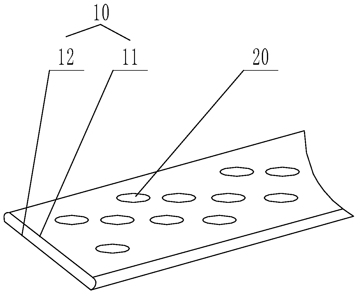
[0042] Such as figure 1 As shown, the radiating pipe of the heat exchanger provided by Embodiment 1 of the present invention includes a pipe body 10 and a dimple 20 provided on the outer wall of the pipe body 10; the dimple 20 includes a plurality of dimples extending in a strip shape; The extending direction of the pit is arranged at an acute or obtuse angle with the extending direction of the pipe body 10 , and a plurality of pits are arranged at intervals along a predetermined direction, and the predetermined direction intersects with the extending direction of the pipe body.
[0043] In this embodiment, in order to ensure a better turbulent flow effect, a plurality of dimples 20 are generally arranged on the outer wall of the pipeline body 10, and the dimples in the dimples 20 extend toward the inner wall of the pipeline body 10, and the pipe body The inner wall of 10 forms a bulge. When the medium flows in the pipe body 10, under the premise of ensuring the general convey...
Embodiment 2
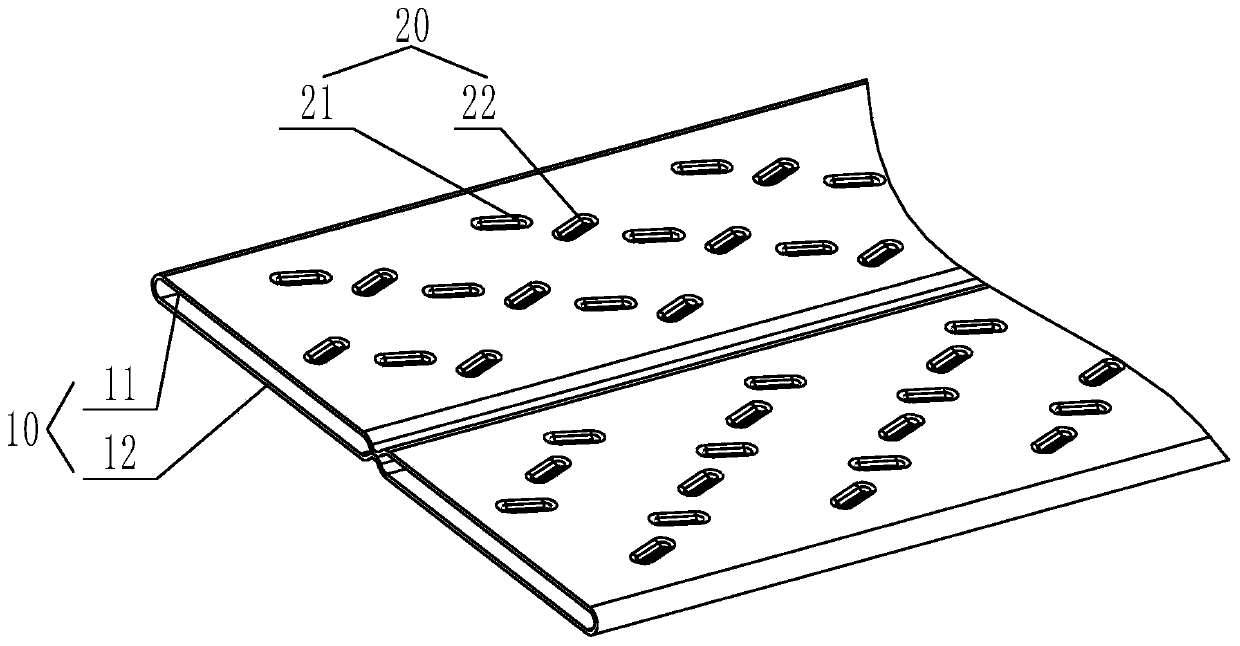
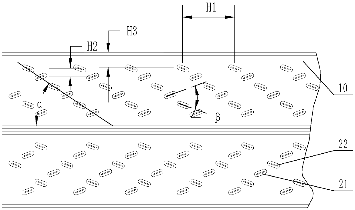
[0059] Such as figure 2 with image 3 As shown, the heat exchanger radiating tube provided by Embodiment 2 of the present invention includes a pipe body 10 and a dimple 20 disposed on the outer wall of the pipe body 10; the dimple 20 includes a plurality of dimples extending in a strip shape; The extending direction of the pit and the extending direction of the pipe body 10 are set at an acute or obtuse angle. At least one of the plurality of pits is the first pit 21 , and at least the other is the second pit 22 , and an angle β is formed between the extending direction of the first pit 21 and the extending direction of the second pit 22 .
[0060] In this embodiment, in order to ensure a better turbulent flow effect, a plurality of dimples 20 are generally arranged on the outer wall of the pipeline body 10, and the dimples in the dimples 20 extend toward the inner wall of the pipeline body 10, and the pipe body The inner wall of 10 forms a bulge. When the medium flows in t...
Embodiment 3
[0086] The main structure of the third embodiment is the same as that of the second embodiment, the difference is that the third embodiment involves the specific structure of the pipe body 10 and the specific arrangement of the dimple 20 on the pipe body 10 . Specifically, as Figure 4 to Figure 6 As shown, the dimple part 20 is arranged at an acute angle or an obtuse angle to the conveying direction of the medium; A plurality of dimples 20 arranged at intervals in the extending direction. In this embodiment, both the upper wall and the lower wall of the pipe body are provided with dimples, which can make the flow of the medium more turbulent and improve the heat exchange performance.
[0087] Wherein, the dimple part on the upper wall is the upper dimple part 1, and the dimple part on the lower wall is the lower dimple part 2, and the upper dimple part 1 and the lower dimple part 2 can be completely oppositely arranged, and also can be partly relative settings.
[0088] As...
PUM
| Property | Measurement | Unit |
|---|---|---|
| Depth | aaaaa | aaaaa |
| Separation distance | aaaaa | aaaaa |
Abstract
Description
Claims
Application Information
 - R&D
- Intellectual Property
- Life Sciences
- Materials
- Tech Scout
- Unparalleled Data Quality
- Higher Quality Content
- 60% Fewer Hallucinations
Browse by: Latest US Patents, China's latest patents, Technical Efficacy Thesaurus, Application Domain, Technology Topic, Popular Technical Reports.
© 2025 PatSnap. All rights reserved.Legal|Privacy policy|Modern Slavery Act Transparency Statement|Sitemap|About US| Contact US: help@patsnap.com


