
Automatic shaping device

A shaping and shaping unit technology, applied in physical therapy, massage aids, non-surgical orthopaedic surgery, etc., can solve the problems of high use cost, high cost of shaping clothing, easy corneal inflammation, etc. Realize the effect of automatic control and correction of myopia

Active Publication Date: 2021-07-02
YICHANG CENT PEOPLES HOSPITAL
View PDF20 Cites 0 Cited by
  • Summary
  • Abstract
  • Description
  • Claims
  • Application Information

AI Technical Summary

Problems solved by technology

However, this solution needs to replace orthokeratology lenses with different diopters, which is very expensive to use, and orthokeratology lenses need to be in contact with the eyeball for a long time, causing problems such as dry eyes and easy inflammation of the cornea, and it is inconvenient to wear and take off
[0003] The postpartum body will be greatly deformed. In the prior art, there are plans to reshape the body by using shapewear. However, as the body changes, shapewear of different sizes needs to be replaced. Personalized and customized shapewear The cost of shape clothing is very high, causing the user's burden

Method used


Image

  • Automatic shaping device
  • Automatic shaping device
  • Automatic shaping device

Examples


Embodiment 1

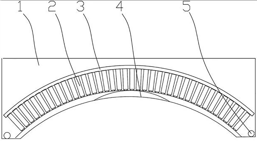
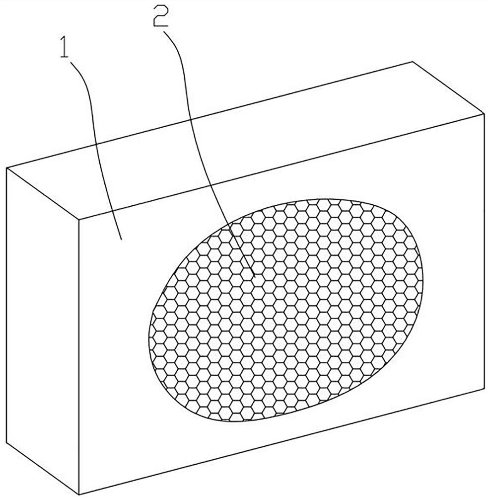
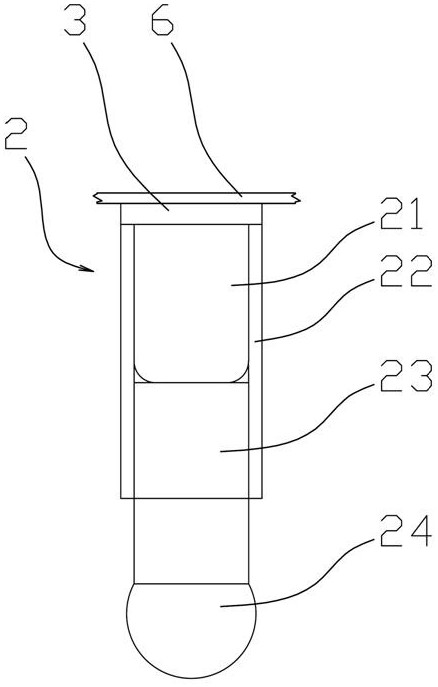
[0027] Such as Figure 1~4 Among them, an automatic shaping device, which includes a base part 1 and a shaping array 2, the shaping array 2 is composed of a plurality of shaping units, and the shaping unit is provided with a retractable pressure head 23, and the shaping array 2 is fixed by the base part 1, and the indenter 73 of the shaping array 2 forms a shape matching the expected shape of the part to be shaped. The molding described here refers to a structure similar to a mould, that is, the expected shape of the part to be molded is spherical, and the shape formed by the indenter 73 is a spherical groove. With this structure, the shaping array 2 can be formed into any desired shape according to the preset parameters, and can be further changed within a certain range to realize gradual shaping until the expected shape of the shaping area is realized. Thereby saving the high cost caused by a large number of customization and individualized production.

[0028] The preferr...

Embodiment 2

[0032] On the basis of Embodiment 1, in a preferred solution, the temperature control component 3 is an electromagnetic coil, and the electromagnetic coil is electrically connected to an alternating current device; the alternating current device preferably adopts an alternating current generated by an inverter. The inverter is a commercially available product.

[0033] A metal sheet for heating is provided between the temperature control component 3 and the deformation capsule 21 ; or multiple metal sheets are provided in the deformation capsule 21 . The alternating magnetic field generated by the alternating current in the electromagnetic coil heats the metal sheet, thereby heating the temperature-sensitive medium, so as to control the volume change of the deformable capsule 21 .

[0034] In a preferred solution, the electromagnetic coil array is arranged, and the electromagnetic coil is electrically connected to the alternating current device through the scanning circuit, an...

Embodiment 3

[0036]On the basis of Example 1, another preferred scheme is as Figure 3~6 In the above, the temperature control component 3 is a semiconductor heating chip, and the semiconductor heating chip is connected to the deformation capsule 21 in a heat conduction manner.

[0037] The preferred solution is as Figure 6 Among them, the semiconductor heating chip is electrically connected to the DC power supply through the scanning circuit, a switch array 8 is arranged on the vertical and horizontal lines of the scanning circuit, the switching array 8 is electrically connected to the main control chip 7, and one end of the semiconductor heating chip is connected to the node of the scanning circuit , and the other end is grounded. With this structure, it is possible to independently control the opening and closing of each semiconductor heating sheet, such as Figure 5 Among them, the heating temperature of the electromagnetic coil is controlled by the pulse signal given by the main co...


PUM


Abstract

The invention provides an automatic shaping device, which includes a base and a shaping array. The shaping array is composed of a plurality of shaping units. The shaping unit is provided with a retractable pressure head. Fix it, and make the shape of the pressure head of the shaping array conform to the expected shape of the part to be shaped. The structure of a single shaping unit in the shaping array is as follows: a deformation capsule is provided in the guide housing, the guide housing and the pressure head are movably socketed, the deformation capsule is located between the guide housing and the pressure head, and the deformation capsule is set There is a temperature-sensitive medium, and the deformation capsule body is connected with the temperature control component in a heat-conducting manner to control the temperature of the temperature-sensitive medium in the deformation capsule body and drive the pressure head to expand and contract. Through the provided shaping parts, the pressure head of each shaping unit in the shaping array can be adjusted to adjust to the expected shape to be shaped. During the wearing process, the to-be-shaped part can be gradually adjusted through the shaping shape.

Description

technical field [0001] The invention relates to a physical therapy auxiliary device, in particular to an automatic shaping device. Background technique [0002] The human body is a highly plastic organism. Experimental and clinical studies have shown that acquired myopia caused by unhygienic eye use is mainly divided into two categories: pseudomyopia and true myopia. The formation of pseudomyopia is mainly during continuous near-distance vision work. In order to make the nearby objects clearly appear on the retina, the ciliary muscle continues to contract to change the lens to adjust the focal length. After a long time, if there is no If you get a timely rest, the ciliary muscle will spasm, so that you can't relax to adjust the shape of the lens to change the focal length when looking far, resulting in blurred vision. The reason why this kind of myopia is called pseudomyopia is that it is only the spasm of the ciliary muscle, and the eyeball has not undergone irreversible ...

Claims


Application Information

Patent Timeline
Patent Type & Authority Patents(China)
IPC IPC(8): A61F9/00A61H7/00A61F5/00
CPCA61F5/00A61F9/00A61H7/00A61H2201/02A61H2205/024
Inventor 易凤仙张真黄星宇刘雪姣刘睿廖晓璐莫纯坚李杰秦双芹陈莹
Owner YICHANG CENT PEOPLES HOSPITAL
Learn More