Flanging machine device

A technology of can pressing machine and inner rod, applied in the field of can pressing machine, can solve the problem of not having a can holding device and the like

Inactive Publication Date: 2019-09-03
ZHEJIANG OCEAN UNIV
View PDF0 Cites 0 Cited by
  • Summary
  • Abstract
  • Description
  • Claims
  • Application Information

AI Technical Summary

Problems solved by technology

[0004] The problem to be solved by the present invention is the problem that none of the current can pressing machines have a tank holding device

Method used


Image

  • Flanging machine device
  • Flanging machine device

Examples


Embodiment Construction

[0012] The present invention will be further described below with reference to the drawings and embodiments.

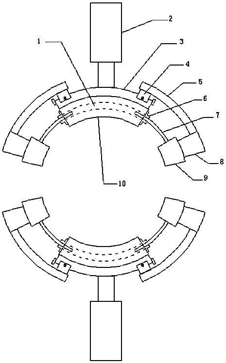
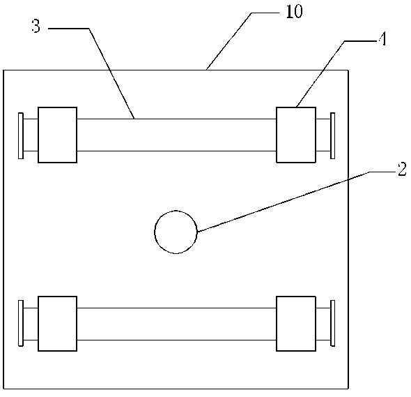
[0013] The present invention is a tank press device, which includes a hollow 1, an electric push rod 2, a sliding rail 3, a sliding block 4, a connecting bending rod 5, a limiting block 6, an inner rod 7, a connecting support rod 8, and a second clamp 9. And the first clamping panel 10, the two first clamping panels 10 are arranged face to face, the first clamping is provided with a hollow 1; one end of the inner rod 7 extends into the hollow 1, and the other end of the inner rod 7 extends out of the hollow 1 1. Outside, the other end of the inner rod 7 is installed with the second clamp 9 panel, the second clamp 9 is installed on the back of the panel with the connecting rod 8, the connecting rod 8 is installed on the side of the connecting rod 5, the connecting rod 5 is installed on the slider 4 On the back, the slider 4 is installed on the slide rail 3. The slider 4 i...


PUM


Abstract

The invention discloses a flanging machine device. The device comprises hollowed-out parts, electric push rods, sliding rails, sliding blocks, connecting bent rods, limiting blocks, inner rods, connecting support rods, second clamping panels and first clamping panels, wherein the two first clamping panels are arranged in a face-to-face manner, the hollowed-out parts are arranged in the first clamping panels, one ends of the inner rods extend into the hollowed-out parts, the other ends of the inner rods extend out of the hollowed-out parts, the other ends of the inner rods are provided with second clamping panels, the backs of the second clamping panels are provided with the connecting support rods, the side surfaces of the connecting supporting rods are provided with the connecting bent rods, the connecting bent rods are arranged on the back surfaces of the sliding blocks, the sliding blocks are arranged on the sliding rails, bolts are arranged on the sliding blocks, the sliding blocksare fixed on the sliding rails through the bolts, piston rods of the electric push rods are installed on the back surfaces of the first clamping panels, the inner rods and the first clamping panels are fixed through the limiting blocks, and the limiting blocks are welded on the first clamping panels and the inner rods. The device has the advantages that a tank body in a flanging process can standstably.

Description

Technical field [0001] The invention relates to a tank press device, belonging to the technical field of tank presses. Background technique [0002] In metal cans, after the can body is closed, the end of the can body needs to be rolled to the outside to enlarge the end to match the recess of the lid body, so that the lid body and the can body can be tightly connected during the sealing. To achieve the sealing effect, none of the current tank presses has a tank holding device, which makes the tank easy to stand unstable during the press process. In order to solve the above-mentioned difficulties, it is necessary to develop a pressing device for the pressing process. Summary of the invention [0003] The object of the present invention is to provide a tank press device. [0004] The problem to be solved by the present invention is that the current tank press does not have the problem of a tank holding device. [0005] In order to achieve the purpose of the present invention, the tec...

Claims


Application Information

Patent Timeline
Patent Type & Authority Applications(China)
IPC IPC(8): B21D43/00B21D51/26
CPCB21D43/003B21D51/2653
Inventor 朱从容
Owner ZHEJIANG OCEAN UNIV
Why Eureka
Try Eureka