
Square box type floating breakwater with oscillating water column type wave energy power generation device

A floating breakwater, oscillating water column technology, applied in breakwaters, ocean energy power generation, jetty and other directions, can solve problems such as increase in size, cost increase, and insignificant wave elimination effect, so as to reduce structural damage and increase service life. , the effect of protecting the structural stability

Inactive Publication Date: 2019-08-30
JIANGSU UNIV OF SCI & TECH
View PDF6 Cites 12 Cited by
  • Summary
  • Abstract
  • Description
  • Claims
  • Application Information

AI Technical Summary

Problems solved by technology

[0004] There are more or less defects in the current breakwaters. For example, according to the current research results, the most important factors affecting the wave dissipation performance of floating breakwaters are the dike width and draft. The wider the dike width and the deeper the draft, the better the wave dissipation. The effect is better, but with the increase of the main scale of the floating breakwater, its cost will increase significantly, and the wave force it receives will also increase, which will place greater requirements on the strength of the structure itself and the design of the mooring system, and Floating breakwaters have a good wave dissipation effect for short-period waves, but not obvious for long-period waves. Therefore, most current engineering applications place floating breakwaters in wave areas with smaller wave heights and shorter periods.

Method used


Image

  • Square box type floating breakwater with oscillating water column type wave energy power generation device
  • Square box type floating breakwater with oscillating water column type wave energy power generation device
  • Square box type floating breakwater with oscillating water column type wave energy power generation device

Examples


Embodiment Construction

[0031] The technical solutions of the present invention will be described in detail below, but the protection scope of the present invention is not limited to the embodiments.

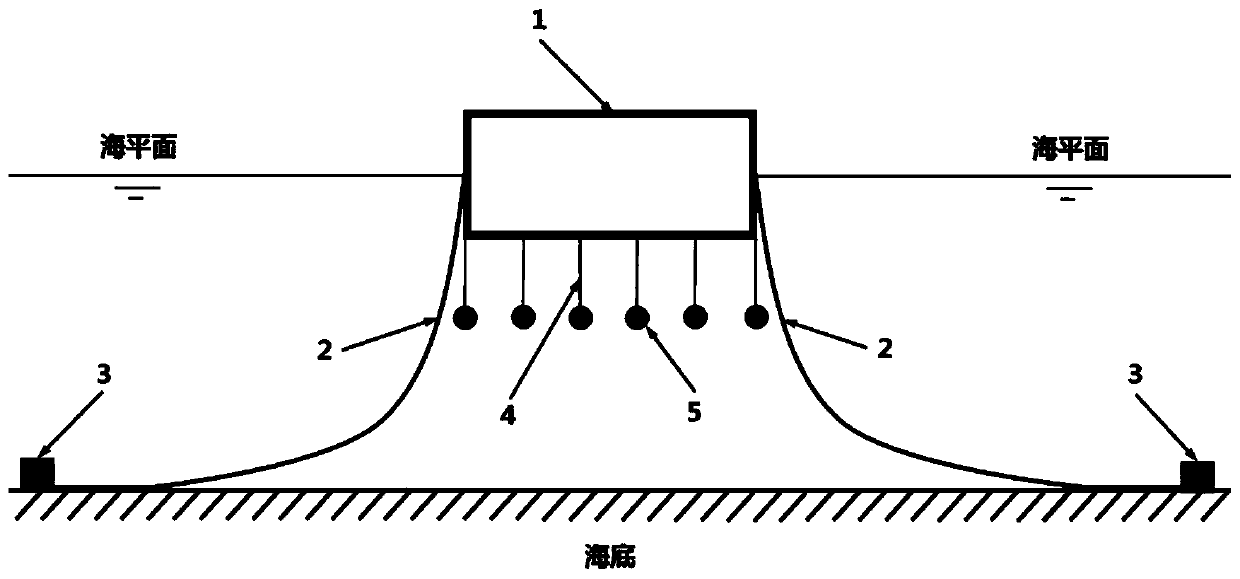
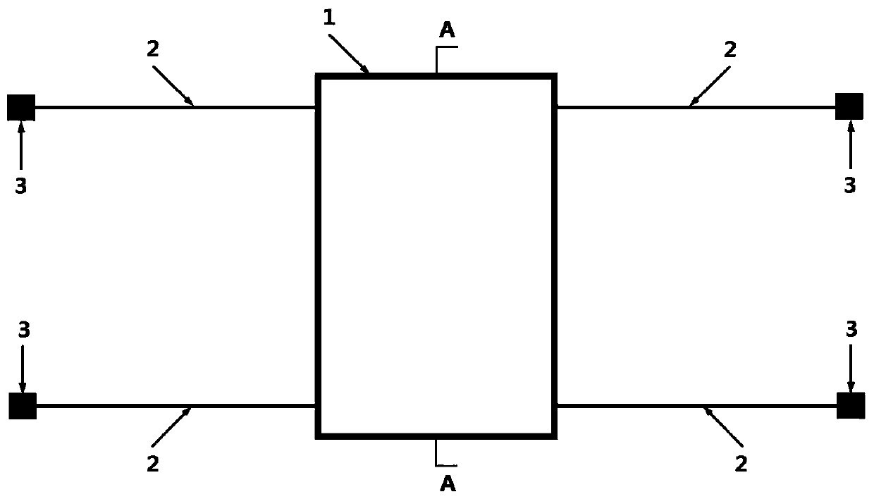
[0032] In the present invention, the box-shaped floating breakwater adopts a catenary mooring system, and the arrangement of the floating breakwater is perpendicular to the main wave direction of the protection area (the incident direction of the wave is 90°), and the main form of its motion response is swaying , heave and roll, as well as tiny surge motions. Therefore, in the mooring system of the present invention, controlling the sway movement of the floating breakwater by the mooring system is the main consideration, and at the same time, the restoring force of the surge of the floating breakwater should also be considered. In order to ensure that the floating breakwater does not experience large-scale sway motion, two anchor chains are arranged on both sides of a single floating breakwater unit. A...


PUM


Abstract

The invention discloses a square box type floating breakwater with an oscillating water column type wave energy power generation device. A wave water inlet is formed in the ahead sea face of the square box type floating breakwater, a generating set is arranged in an airflow channel, waves enter an air chamber from the water inlet of the ahead sea face of the square box type floating breakwater, and a water column which oscillates up and down is formed; the water column oscillates up and down to force air in the air chamber to be compressed and expanded, the air passes through the airflow channel on the top of the air chamber in a reciprocated manner, the generating set is pushed to generate power, through a transmission device, the electric quantity is stored in an energy storage device for standby application, and the breakwater has the advantages of being simple and stable in structure, low in building cost, high in power generation conversion efficiency, convenient to maintain, highin adaptation and the like and can be arranged on the coast, nearshore or offshore sea area, the ocean space is effectively used, the wave energy is converted into electric energy while the wave influence is reduced, and the stable water area environment is provided for the surrounding sea area, and the ocean wave resources are reasonably used.

Description

technical field [0001] The invention belongs to the technical field of marine engineering, and in particular relates to a square box-type floating breakwater with an oscillating water column type wave energy generating device. Background technique [0002] In order to solve the current energy supply problem that is essential for human development, it has gradually become the consensus of all countries in the world to find alternative, renewable, and clean new energy sources. New energy sources include ocean energy, biomass energy, wind energy, solar energy, geothermal energy, nuclear energy, etc. Ocean energy has attracted the attention of scientific researchers from all over the world because of its unique charm. As we all know, the surface of the earth is separated by major continents into vast waters connected to each other called oceans, with a total area of ​​about 360 million square kilometers, accounting for about 71% of the earth's surface area, and an average water ...

Claims


Application Information

Patent Timeline
IPC IPC(8): E02B3/06F03B13/24
CPCE02B3/062F03B13/142Y02A10/11Y02E10/30
Inventor 崔杰柳辉嵇春艳李千李子超
Owner JIANGSU UNIV OF SCI & TECH
Learn More