
Air guiding apparatus for motor vehicle body

A technology for air guidance and motor vehicles, which is applied in the direction of the body, body stability, and vehicle components, etc., and can solve the problems of increased air resistance of the motor vehicle body, achieve position stability, and reduce fuel consumption.

Active Publication Date: 2019-08-30
DR ING H C F PORSCHE AG
View PDF15 Cites 0 Cited by
  • Summary
  • Abstract
  • Description
  • Claims
  • Application Information

AI Technical Summary

Problems solved by technology

[0004] As soon as the rear wing protrudes from the flush position with the motor vehicle body, as is often the case during driving operation, edge vortices are generated at the lateral ends of the rear wing, which in turn lead to an increased air resistance of the motor vehicle body

Method used


Image

  • Air guiding apparatus for motor vehicle body
  • Air guiding apparatus for motor vehicle body
  • Air guiding apparatus for motor vehicle body

Examples


Embodiment Construction

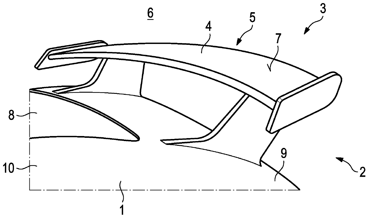
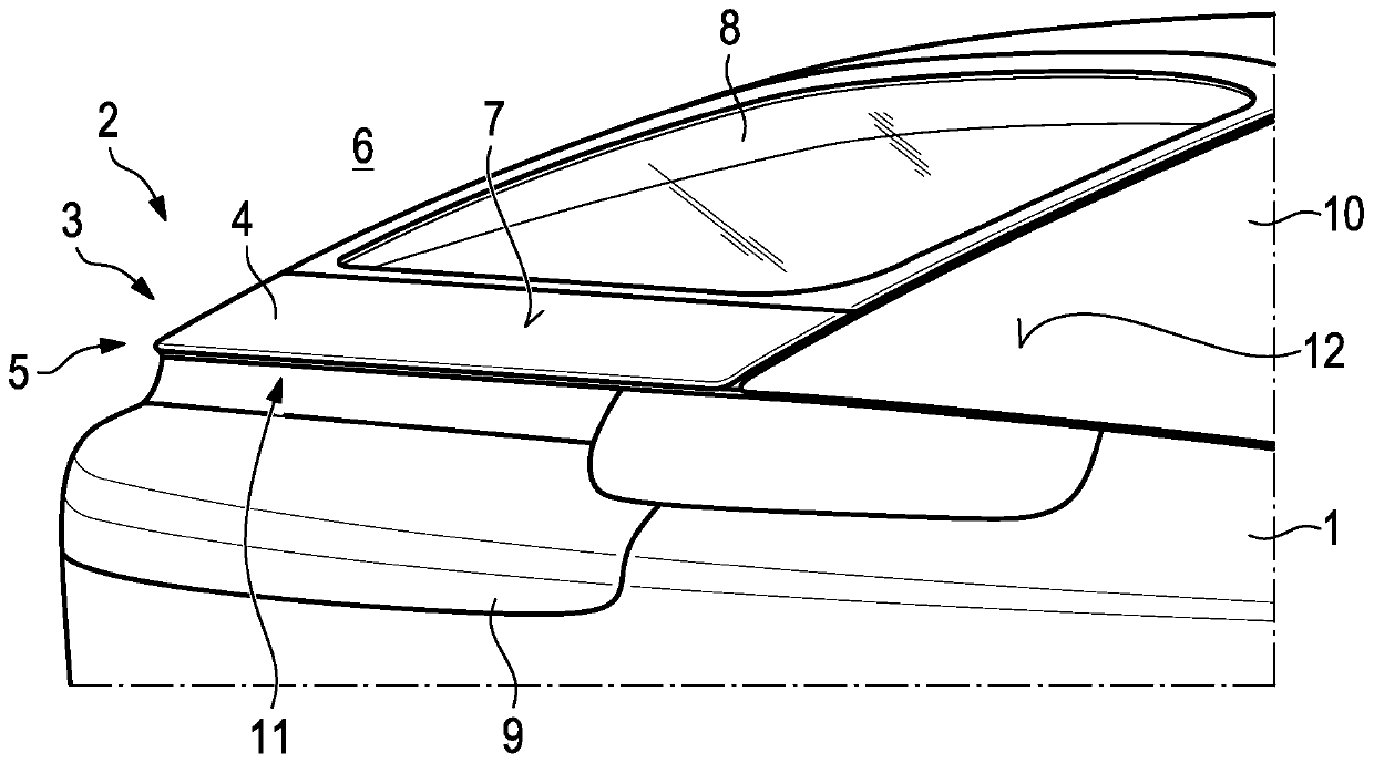
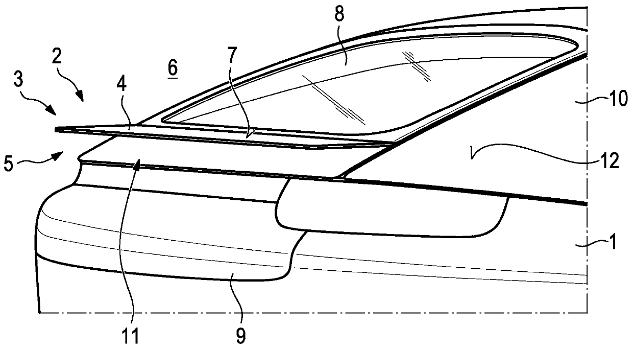
[0056] Motor vehicle body 1, which is in accordance with figure 1 In the first example of and based on figure 2 and 3 Implementation in a second example of a motor vehicle comprising an air guiding device 3 according to the prior art arranged in the rear region 2 of a motor vehicle body 1 .

[0057] The air guiding device 3 is adjustable from a first operating state to a second operating state. In particular, the air drag coefficient and the downforce of the motor vehicle body 1 can be varied by means of the air guiding device 3 . The air-guiding device 3 comprises at least one air-guiding element 4 for flow guiding, which is connected to an adjustment device 5 . The air guiding element 4 is designed in the form of an empennage and is also referred to as an airfoil. In particular, the airfoil surface 7 of the airfoil 4 which is designed to face the surroundings 6 is designed aerodynamically.

[0058] In the rear region 2 , the motor vehicle body 1 has a rear window 8 and...


PUM


Abstract

The invention relates to an air guide device for a motor vehicle body. An air guiding element (4) of the air guiding device (3) can be movably accommodated in the motor vehicle body (1) by means of anadjusting device (5), and can be brought into at least a first position and a second position, wherein the air guide element (4) is accommodated in the motor vehicle body (1) in a first position andencloses an angle with the motor vehicle body (1) with a value of less than 360 DEG in a second position, wherein the air guide element (4) is designed to extend in the direction of the vehicle transverse axis (18), and wherein the air guide device (3) has a further air guide element (15), which is designed to extend in the direction of the vehicle longitudinal axis (19) in the active position thereof. According to the invention, a further air-guiding element (15) is designed to be displaceable and can be at least partially accommodated in the air-guiding element (4).

Description

technical field [0001] The invention relates to an air guiding device for a motor vehicle body. Background technique [0002] Air-guiding devices comprising air-guiding elements for motor vehicle bodies are known. The air guiding element is in particular a so-called rear wing which is movably accommodated on the motor vehicle body so that it can assume different positions relative to the motor vehicle body between a first end position and a second end position. In the first end position, the rear wing is arranged flush with the motor vehicle body, wherein in the second end position, the rear wing is at a maximum distance from the motor vehicle body. In particular, the downforce of a motor vehicle with a motor vehicle body during operation can be varied by means of the spoiler. [0003] The movable fin is connected to an adjustment device of the air guiding device, which moves the fin into its respective position to be assumed and holds it in this position. The adjustment ...

Claims


Application Information

Patent Timeline
Patent Type & Authority Applications(China)
IPC IPC(8): B62D35/00
CPCB62D35/007B62D35/008B62D37/02Y02T10/82
Inventor M·辛特伯西格
Owner DR ING H C F PORSCHE AG
Learn More