Battery pole piece forming device

A technology for forming devices and battery pole pieces, which is applied in metal processing and other directions, can solve the problems of limited accuracy of response time, gaps, and long intermediate processes, etc., and achieve the effect of improving retention time, service life, and precise time coordination

Inactive Publication Date: 2019-08-30
谢敬群
View PDF7 Cites 0 Cited by
  • Summary
  • Abstract
  • Description
  • Claims
  • Application Information

AI Technical Summary

Problems solved by technology

[0003] When the eccentric wheel drives the connecting rod, there will be a large radial force, and there will be greater wear and tear between the eccentric wheel and the connecting rod, resulting in gaps, which will affect the production quality of the pole piece. Secondly, the direct connection shaft between the eccentric wheel and the motor It will also bear a large vertical force, reducing the service life of the motor and the connecting shaft. In addition, the vertical displacement driven by the eccentric wheel is fixed, and the stamping cannot be completed when the die is worn to a certain extent, which in turn affects the service life of the die.
[0004] The above-mentioned eccentric wheel structure controls the cutting die by controlling the speed of the servo motor and then controlling the speed of the eccentric wheel, and then transmits the control command to the cutting die through the connecting rod. On the one hand, the intermediate process is long and the response time is slow. The processing speed of the forming device is also limited. On the other hand, the accuracy of the response time of the control command is also limited after multiple transmissions, which may cause a mismatch between the stamping time of the knife die and the running time of the pole piece, and ultimately affect the production accuracy.

Method used


Image

  • Battery pole piece forming device
  • Battery pole piece forming device
  • Battery pole piece forming device

Examples


Embodiment Construction

[0022] The following will clearly and completely describe the technical solutions in the embodiments of the present invention with reference to the accompanying drawings in the embodiments of the present invention. Obviously, the described embodiments are only some, not all, embodiments of the present invention. Based on the embodiments of the present invention, all other embodiments obtained by persons of ordinary skill in the art without making creative efforts belong to the protection scope of the present invention.

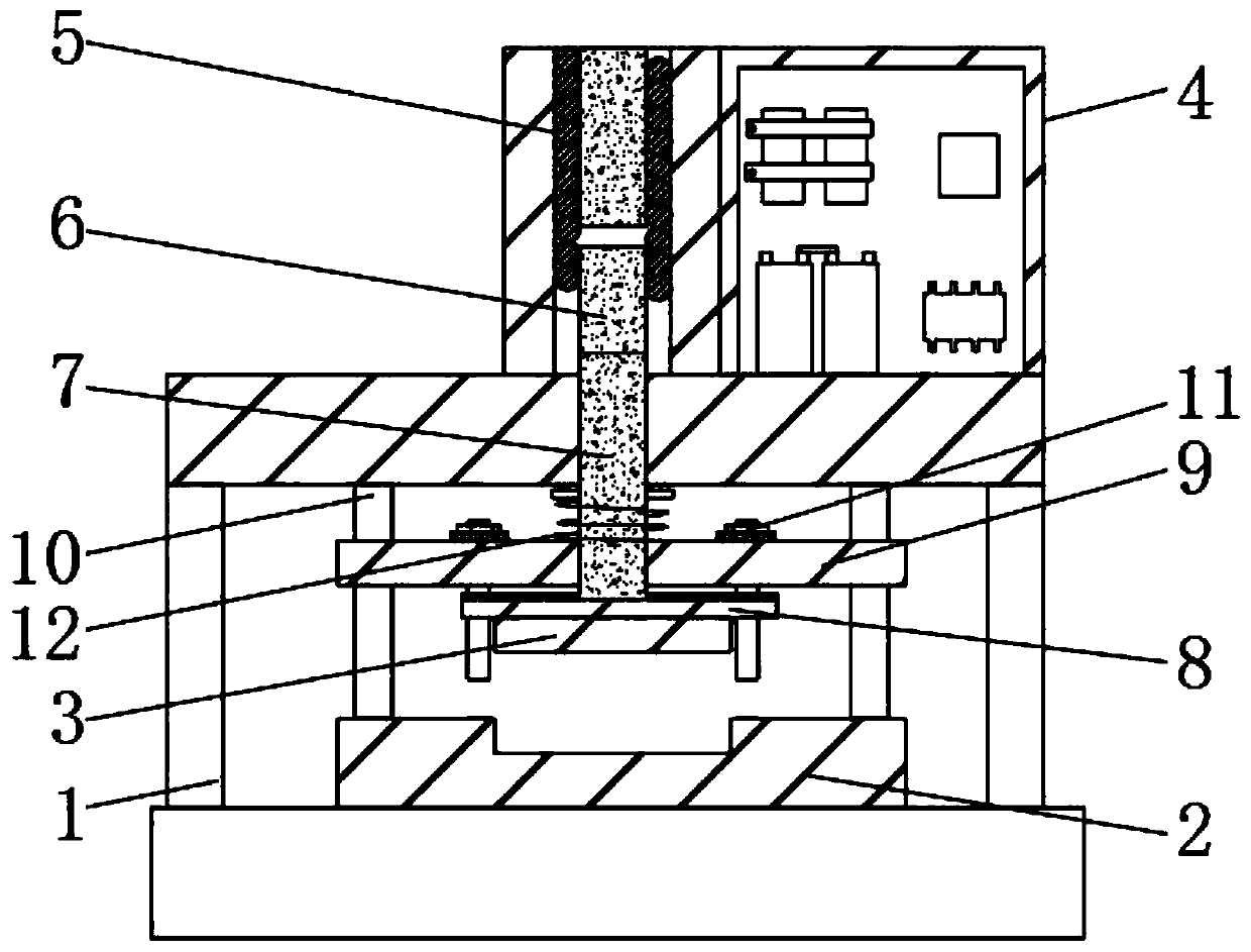
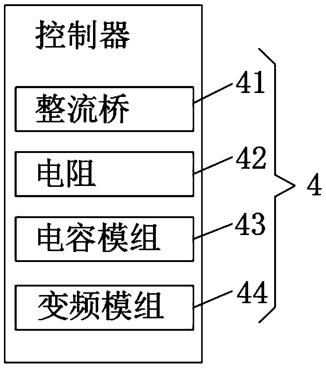
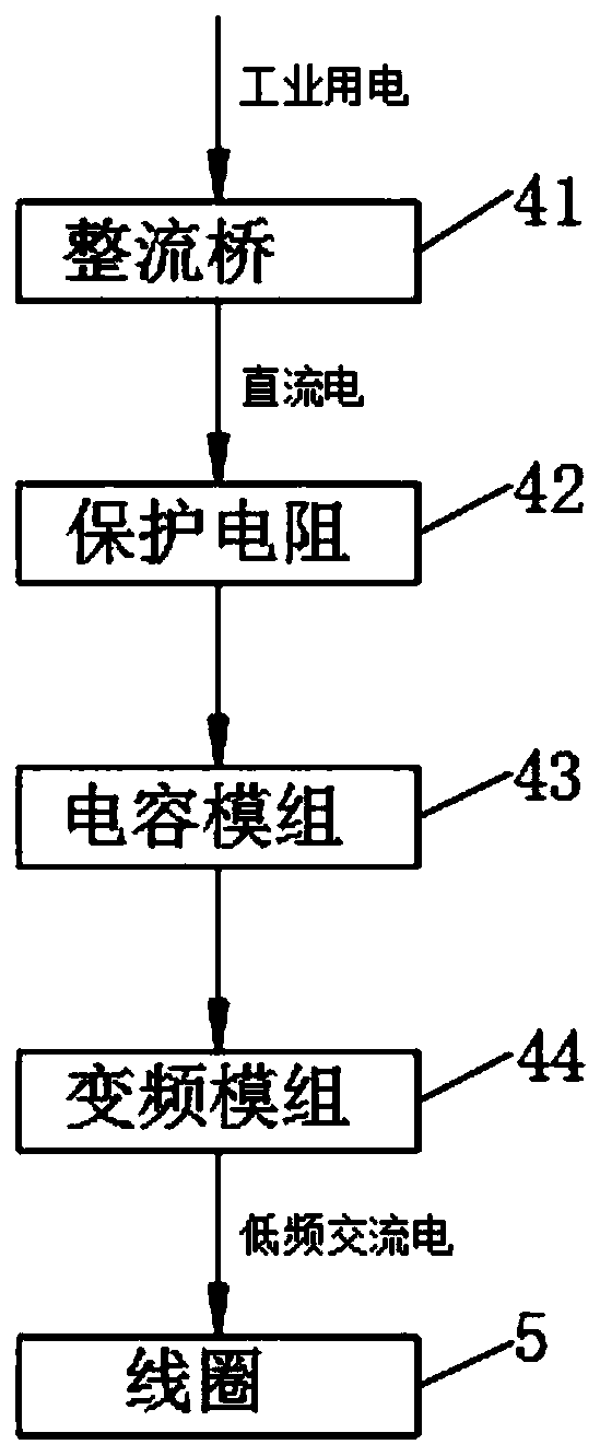
[0023] see Figure 1-5 , a battery pole piece forming device, comprising a frame 1, the lower end of the frame 1 is provided with a lower die 2, the upper end of the lower die 2 is provided with a knife die 3, and the outer surface of the frame 1 is provided with a controller 4, through the control The device 4 controls the magnitude and direction of the current input to the coil 5, and controls the generation of magnetic force. The coil 5 with iron core is in...


PUM


Abstract

The invention relates to the technical field of battery processing equipment, and discloses a battery pole piece forming device which comprises a rack. A lower die is arranged at the lower end of therack, a cutter die is arranged at the upper end of the lower die, a controller is arranged on the outer surface of the rack, and a coil with an iron core is mounted on the upper end surface of the rack. According to the battery pole piece forming device, a connecting rod is driven by the coil to drive a cutter die to punch a battery pole piece, only the connecting rod bears the vertical driving force and the reaction force when the pole piece is punched, the abrasion of the outer side wall of the battery pole piece forming device is far less than that of a conventional device, the retention time of the processing precision of the battery pole piece forming device is prolonged, the redundant driving force generated when the battery pole piece is punched is borne by a positioning block, theservice life of the cutter die is prolonged, besides, when the thickness of the cutter die is abraded to a certain degree, the displacement of the cutter die can be adjusted through an inner positioning rod to enable the cutter die to continue to be used, the connecting rod and the cutter die are directly driven to move through the coil, and the control precision of the processing time of the device is improved.

Description

technical field [0001] The invention relates to the technical field of battery processing equipment, in particular to a battery pole piece forming device. Background technique [0002] The production process of battery pole pieces includes coating, rolling and forming. The forming process is usually punched by a die-cutting machine. The traditional die-cutting machine usually uses a servo-driven eccentric wheel to drive a connecting rod to drive a knife die to stamp out pole pieces. , has the advantages of fast speed, high precision and low noise. [0003] When the eccentric wheel drives the connecting rod, there will be a large radial force, and there will be greater wear and tear between the eccentric wheel and the connecting rod, resulting in gaps, which will affect the production quality of the pole piece. Secondly, the direct connection shaft between the eccentric wheel and the motor It will also bear a large vertical force, reducing the service life of the motor and t...

Claims


Application Information

Patent Timeline
Patent Type & Authority Applications(China)
IPC IPC(8): B26F1/40B26D5/00B26D5/08
CPCB26D5/005B26D5/086B26F1/40
Inventor 谢敬群
Owner 谢敬群
Why Eureka
Try Eureka