
Self-stabilization plane micro grinding device

A grinding device and self-stabilizing technology, applied in portable grinding machines, grinding machines, grinding/polishing equipment, etc., can solve the problem of not being suitable for small area grinding, and achieve the effect of simple structure, convenient use, and avoidance of tilting

Pending Publication Date: 2019-08-30
NANJING UNIV OF AERONAUTICS & ASTRONAUTICS
View PDF0 Cites 0 Cited by
  • Summary
  • Abstract
  • Description
  • Claims
  • Application Information

AI Technical Summary

Problems solved by technology

[0002] Grinding device is an indispensable tool in daily life. Whether it is processing parts in factories, college students making competitions, or doing patch tests in scientific research, grinding devices will be used, but the most common ones in life are slightly larger grinding devices. , is more suitable for large-area grinding of large-volume parts, but not suitable for small-area grinding such as patch testing, so a micro-grinding device needs to be designed and used

Method used

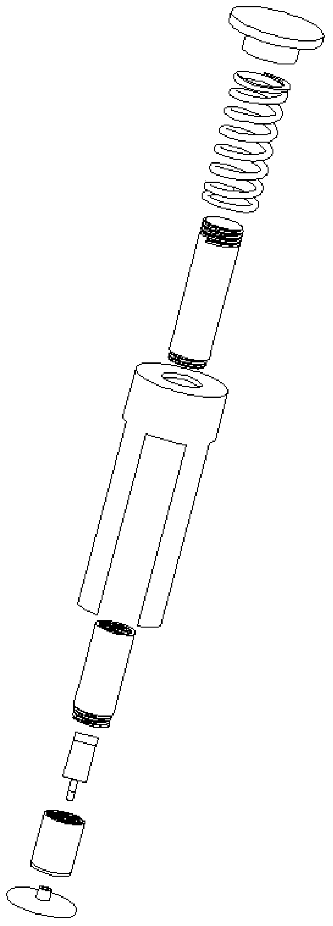
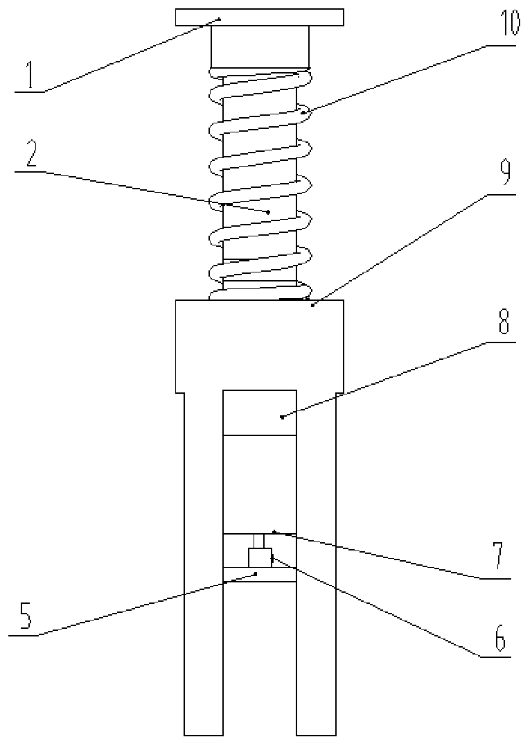

Image

  • Self-stabilization plane micro grinding device
  • Self-stabilization plane micro grinding device
  • Self-stabilization plane micro grinding device

Examples


Embodiment Construction

[0022] Embodiments of the present invention are described in detail below, examples of which are shown in the drawings, wherein the same or similar reference numerals denote the same or similar elements or elements having the same or similar functions throughout. The embodiments described below by referring to the figures are exemplary only for explaining the present invention and should not be construed as limiting the present invention.

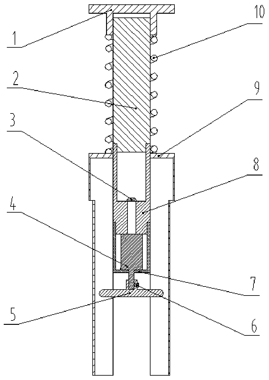
[0023] like figure 1 , figure 2 , image 3 As shown, a self-stabilizing plane micro-grinding device comprises a pressure handle 1, a spring 10, a connecting rod 2, a self-stabilizing bracket 9, an electrode piece 3, a battery box 8, a small motor 4, a motor box 7 and a micro-grinding wheel 5, and the pressure The handle 1 is threadedly connected to the upper end of the connecting rod 2, the inner ring of the spring 10 is sleeved on the outer cylindrical surface of the connecting rod 2, the upper end of the spring 10 is in contact with th...


PUM

PropertyMeasurementUnit
Central angleaaaaaaaaaa

Abstract

The invention discloses a self-stabilization plane micro grinding device. The self-stabilization plane micro grinding device comprises a pressing handle, a spring, a connecting rod, a self-stabilizingsupport, an electrode plate, a battery box, a small motor, a motor box and a micro grinding wheel. The pressing handle is in threaded connection with the upper end of the connecting rod, the spring is sleeved on an outer cylindrical surface of the connecting rod, the upper end of the spring is in contact with the lower end surface of the pressing handle, the lower end of the spring is in contactwith the upper end surface of a self-stabilizing support, the lower end of the connecting rod is in threaded connection with the upper end of the battery box, the lower end of the connecting rod is inthreaded connection with the upper end of the battery box, in a working state, the outer wall of the connecting rod is in sliding contact with the inner surface of a round hole of the support, the electrode plate is welded to the bottom end of the battery box, the outer cylindrical surface of the battery box is in sliding contact with the inner surface of the round hole of the support, the lowerend of the battery box is connected to the upper end of the motor box through threads, a constraint groove is formed in the bottom end of an inner cavity of the motor box, the inner wall of the motorbox is in interference fit with the shell surface of the small motor, and the output end of the small motor is in transition fit with the micro grinding wheel. According to the self-stabilization plane micro grinding device, the small-area plane can be subjected to micro-grinding, the grinding precision is high, the self-stabilizing function is achieved, and the inclination of the grinding surfaceis avoided.

Description

technical field [0001] The invention relates to a plane micro-grinding device, in particular to a self-stabilizing plane micro-grinding device, which belongs to the technical field of mechanical processing equipment. Background technique [0002] Grinding device is an indispensable tool in daily life. Whether it is processing parts in factories, college students making competitions, or doing patch tests in scientific research, grinding devices will be used, but the most common ones in life are slightly larger grinding devices. , is more suitable for large-area grinding of large-volume parts, but not suitable for the situation where small-area grinding is required for patch testing, so a micro-grinding device remains to be designed and used. Contents of the invention [0003] The technical problem to be solved by the present invention is to provide a self-stabilizing plane micro-grinding device, which can micro-grind a small-area plane and has a self-stabilizing function. ...

Claims


Application Information

Patent Timeline
IPC IPC(8): B24B23/02B24B23/00
CPCB24B23/02B24B23/005
Inventor 丁景伟靳广虎
Owner NANJING UNIV OF AERONAUTICS & ASTRONAUTICS
Learn More