Punching machine and robot used for punching machine

A punching machine and robot technology, applied in the field of mechanical equipment, can solve the problems of dangerous punching work, waste of punching machine value, and safety, etc., and achieve the effects of multiple uses, high use value, and accurate positioning.

Inactive Publication Date: 2019-08-30
常州市思企智能科技有限公司
View PDF6 Cites 0 Cited by
  • Summary
  • Abstract
  • Description
  • Claims
  • Application Information

AI Technical Summary

Problems solved by technology

[0002] At present, the stamping machine in the market has a relatively single function, and only one kind of processing can be realized for punching, folding, and film lamination. The value of the stamping machine is relatively wasteful, and the stamping work is more dangerous. Easy to hurt fingers, there is a safety hazard

Method used


Image

  • Punching machine and robot used for punching machine
  • Punching machine and robot used for punching machine
  • Punching machine and robot used for punching machine

Examples


Embodiment Construction

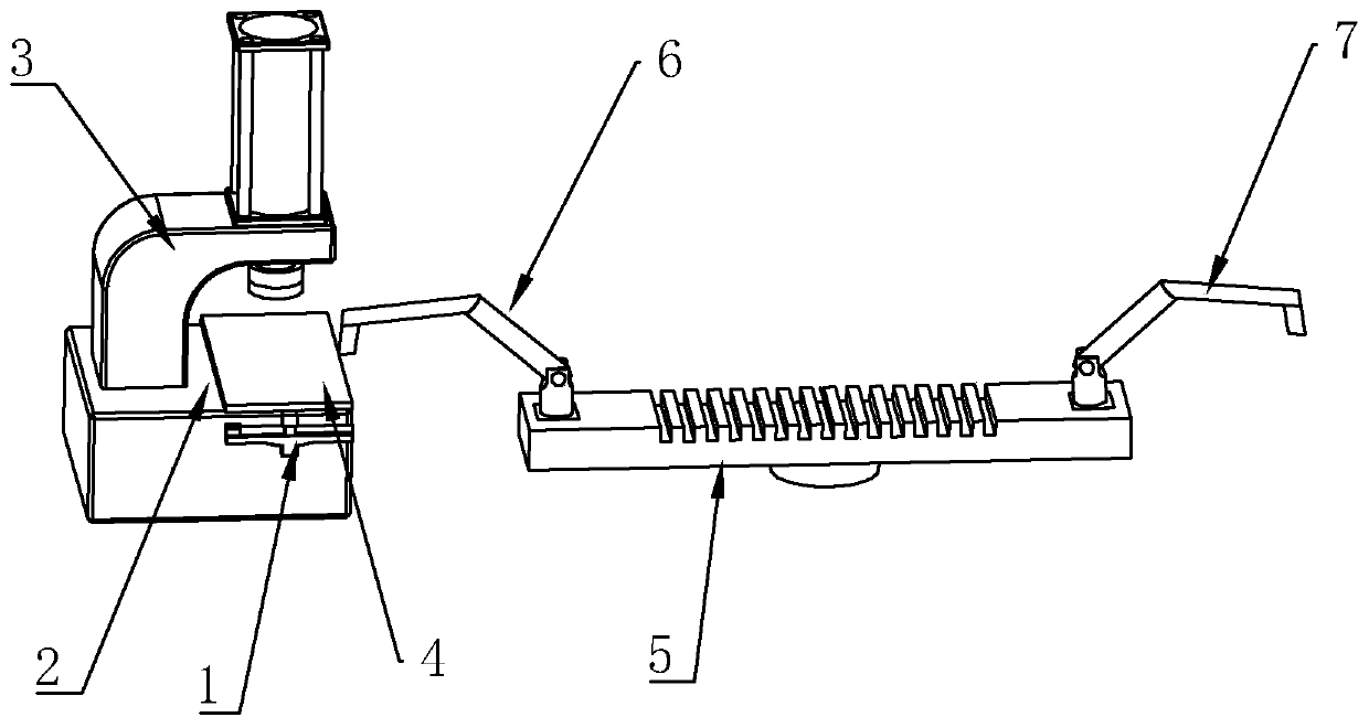
[0025] Refer to attached Figures 1 to 3 The punching machine of the present invention and the robot embodiment for the punching machine will be further described.

[0026] A stamping machine, comprising a faucet support 3, a first hydraulic cylinder and a travel switch, the faucet support 3 includes a cantilever and a workbench 2 below the cantilever, the first hydraulic cylinder is fixed on the cantilever, and the travel switch controls the piston of the first hydraulic cylinder The up and down telescopic and telescopic travel of the rod, the base plate 4 and the moving device 1 for translationally moving the base plate 4 are arranged on the workbench 2. The moving device 1 includes a T-shaped support frame, an X-axis moving mechanism and a Y-axis moving mechanism, and the X-axis moves The mechanism includes an X-axis motor, an X-axis screw and an X-axis screw seat. The X-axis motor is fixed at one end of the support frame. One end of the X-axis screw is fixedly connected to...


PUM


Abstract

The invention discloses a punching machine and a robot used for the punching machine. The punching machine comprise a faucet-shaped support, a first hydraulic cylinder and a travel switch, wherein thefaucet-shaped support comprises a cantilever and a workbench arranged below the cantilever, the first hydraulic cylinder is fixed on the cantilever, the travel switch controls the first hydraulic cylinder to stretch and retract, a base plate and a traveling device used for horizontally moving the base plate are arranged on the workbench, fixing devices used for fixing metal plates are arranged ontwo sides of the workbench, a conveying device is arranged on one side of the workbench, the two ends of the conveying device are respectively provided with a loading head and a feeding head, and thefeeding head consists of a multi-section mechanical arm, a base and arm claws. The traveling device moves front, back, left and right, so that the stamping range of a stamping head is wider under themoving condition, the metal plates are not easy to shake on the workbench by the fixing devices, the loading head and the feeding head replace manual filling of the punching machine, the working efficiency is improved, the safety factor is high, work injuries cannot be caused, the conveying device is used for arranging the metal plates between the loading head and the feeding head, and manpower is saved.

Description

technical field [0001] The present invention relates to a mechanical device, and more particularly, to a punching machine and a robot used for the punching machine. Background technique [0002] At present, the stamping machine in the market has a relatively single function, and only one kind of processing can be realized for punching, folding, and film lamination. The value of the stamping machine is relatively wasteful, and the stamping work is more dangerous. It is easy to injure fingers and pose a safety hazard. Contents of the invention [0003] In view of the deficiencies in the prior art, the purpose of the present invention is to provide a stamping machine and a robot used for the stamping machine, which have the characteristics of multiple functions and safety. [0004] To achieve the above object, the present invention provides the following technical solutions: [0005] A stamping machine, comprising a faucet support, a first hydraulic cylinder and a travel sw...

Claims


Application Information

Patent Timeline
IPC IPC(8): B21D22/00B21D43/02
CPCB21D22/00B21D43/02
Inventor 张小赛左涛
Owner 常州市思企智能科技有限公司
Why Eureka
Try Eureka