Induction electrostatic atomization nozzle

An electrostatic atomization and nozzle technology, applied in induction discharge spraying, electrostatic spraying device, spraying device, etc., can solve the problems of endangering operator safety, unstable charging effect of electrostatic spraying system, hidden danger of electrical safety, etc., to reduce the electric field. Intensity, the effect of avoiding the phenomenon of droplet adsorption

Active Publication Date: 2019-08-30
JIANGSU UNIV
View PDF7 Cites 10 Cited by
  • Summary
  • Abstract
  • Description
  • Claims
  • Application Information

AI Technical Summary

Problems solved by technology

During the spraying process, because the charge carried by the high-voltage electrode device and the charge of the liquid droplets are different charges, part of the liquid droplets sprayed from the nozzle will be directly adsorbed on the surface of the high-voltage electrode device, and some liquid droplets will be on the surface of the high-voltage electrode device. Under the action of electric charge attraction (external electric field), after going back from the outer space of the nozzle body, it is adsorbed on the outer surface of the nozzle body. This phenomenon that the charged droplets are adsorbed on the surface of the high-voltage electrode device and the outer surface of the nozzle body is called the droplet adsorption phenomenon. It is easy to cause problems such as unstable charging effect, liquid leakage and high-voltage discharge in the electrostatic spray system, forming electrical safety hazards and endangering the safety of operators
At present, some domestic patents have designed a special coating structure such as an insulating layer on the outside of the electrode device to enhance the insulation effect of the high-voltage electrode device, but the impact of the coating structure such as the insulating layer on the external electric field strength of the electrode is very small, and there is no improvement. droplet adsorption

Method used


Image

  • Induction electrostatic atomization nozzle
  • Induction electrostatic atomization nozzle
  • Induction electrostatic atomization nozzle

Examples


Embodiment Construction

[0042] The present invention is described in further detail now in conjunction with accompanying drawing. These drawings are all simplified schematic diagrams, which only illustrate the basic structure of the present invention in a schematic manner, so they only show the configurations related to the present invention.

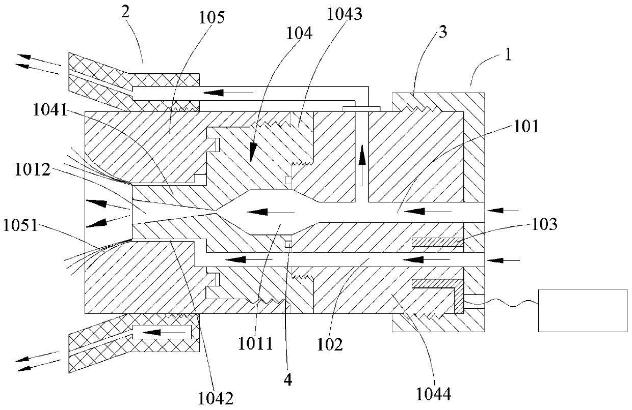
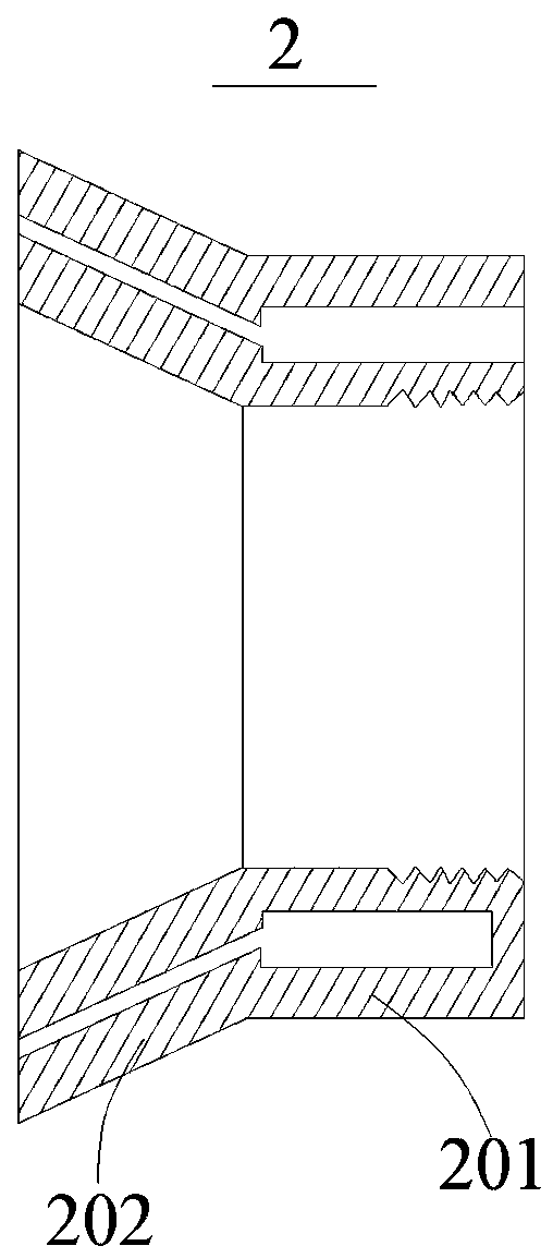
[0043] Such as Figure 1~3 As shown, an induction electrostatic atomization nozzle of the present invention includes a nozzle body 1, the nozzle body 1 has an internal gas flow channel 101, and a liquid flow channel 102 surrounding the internal gas flow channel 101;

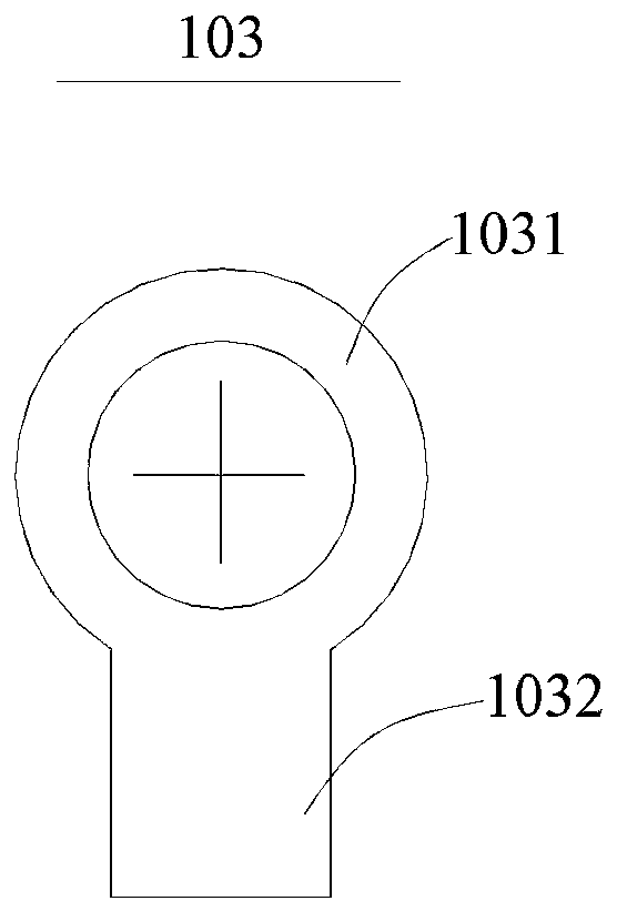
[0044] An electrode ring 103 is disposed around the liquid flow channel 102 at the inlet of the liquid flow channel 102 .

[0045] This kind of induction electrostatic atomization nozzle, by placing the electrode ring 103 at the inlet end of the liquid flow channel 102, ensures that the electrode ring 103 is far away from the position of the induction electrostatic atomization nozzle, thereby re...


PUM


Abstract

The invention relates to an induction electrostatic atomization nozzle. The induction electrostatic atomization nozzle comprises a nozzle body, wherein the nozzle body is provided with an internal gasflow channel, the liquid flow channel is located at the inlet of a liquid flow channel, and the liquid flow channel is provided with an electrode ring. According to the induction electrostatic atomization nozzle, the electrode ring is arranged at the inlet end of the liquid flow passage, the position of the electrode ring far away from the induction electrostatic atomization nozzle is guaranteed,and thus the electric field intensity at the position of an induction electrostatic atomization spray head is reduced, and the fog drop adsorption phenomenon is avoided to a certain extent.

Description

technical field [0001] The invention relates to a nozzle, in particular to an induction electrostatic atomization nozzle. Background technique [0002] Electrostatic atomization is an advanced atomization technology widely used in the fields of agricultural plant protection spray application, industrial spray combustion and drying, etc., especially in the field of agricultural plant protection spray application technology, which combines airflow-assisted atomization technology and induction electrostatic fog The inductive electrostatic atomizing nozzle of the chemical technology is a plant protection spraying part with chemical-saving, water-saving, high-efficiency atomization and anti-drift performance. [0003] At present, the spray patterns of the existing air-assisted induction electrostatic atomization nozzles at home and abroad are all solid conical. The periphery of the circular hole is sprayed out at high speed to form a jet stream, which enhances the atomization an...

Claims


Application Information

Patent Timeline
Patent Type & Authority Applications(China)
IPC IPC(8): B05B5/03B05B5/053
CPCB05B5/03B05B5/0533B05B5/043B05B7/0815B05B1/06
Inventor 欧鸣雄汪明吴敏敏贾卫东杨学军龚辰周慧涛
Owner JIANGSU UNIV
Why Eureka
Try Eureka