
Efficient treatment system of polluting air source

A technology of processing system and gas source, applied in the field of high-efficiency processing system of polluted gas source, can solve problems such as large equipment space, unfavorable environmental protection, environmental pollution, etc., to avoid waste of energy and resources, and ensure completeness and stability , the effect of working closely

Pending Publication Date: 2019-08-30
苏州仕净科技股份有限公司
View PDF23 Cites 0 Cited by
  • Summary
  • Abstract
  • Description
  • Claims
  • Application Information

AI Technical Summary

Problems solved by technology

[0002] In the prior art, the treatment devices for polluted gas sources are relatively simple, and the purification of many polluted gases usually fails to achieve the expected effect, which is not conducive to environmental protection
In addition, the emission of polluted gas sources will not remain constant. In order to ensure that it can be completely processed, the purification equipment is usually made very large, which not only takes up a large equipment space, but also wastes part of the processing capacity of the purification equipment. , which increases the processing cost of the polluted air source; in addition, after the polluted air source is purified by a single treatment device, it is difficult to achieve complete purification, and if it is discharged into the air, it will still cause slight pollution to the environment

Method used


Image

  • Efficient treatment system of polluting air source
  • Efficient treatment system of polluting air source
  • Efficient treatment system of polluting air source

Examples


Embodiment Construction

[0047] The present invention will be further described in detail below in conjunction with the accompanying drawings, so that those skilled in the art can implement it with reference to the description.

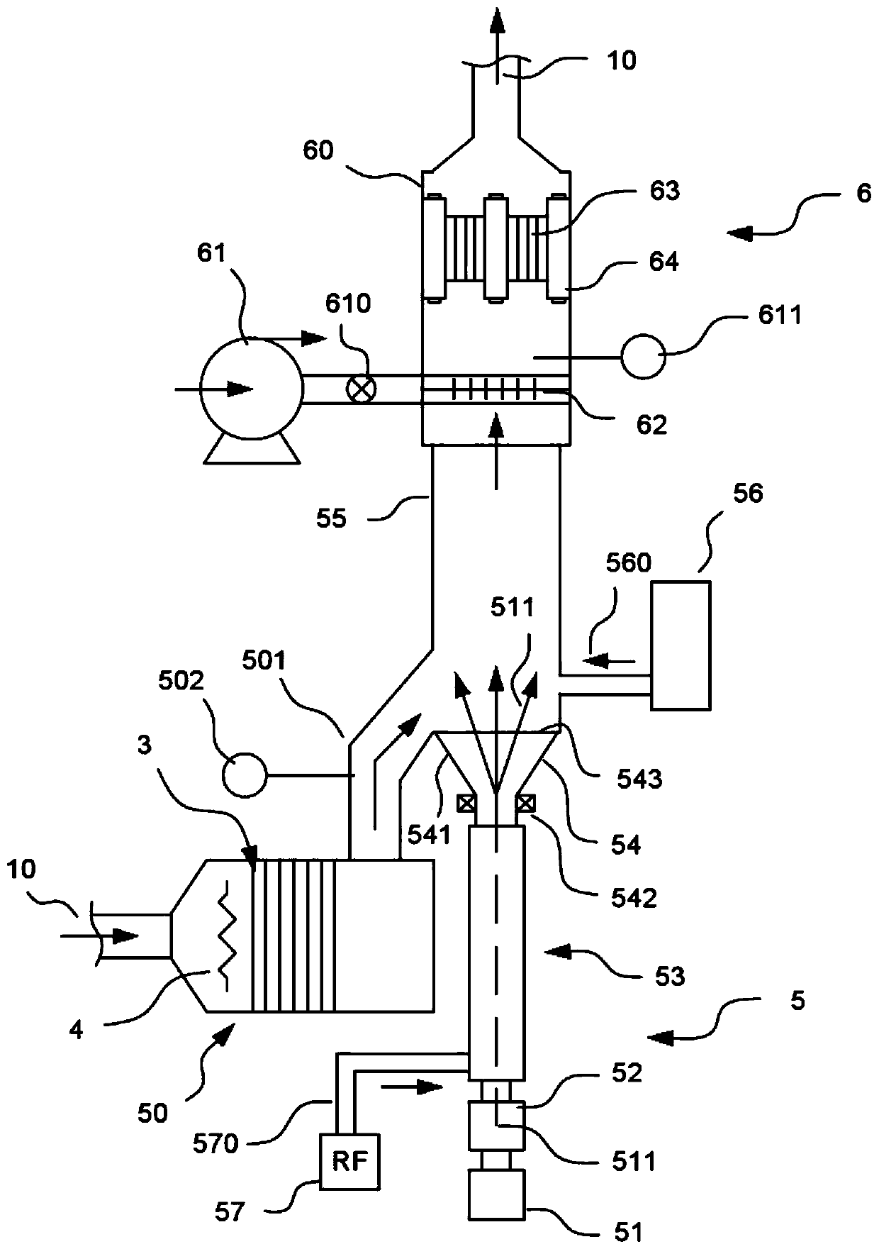
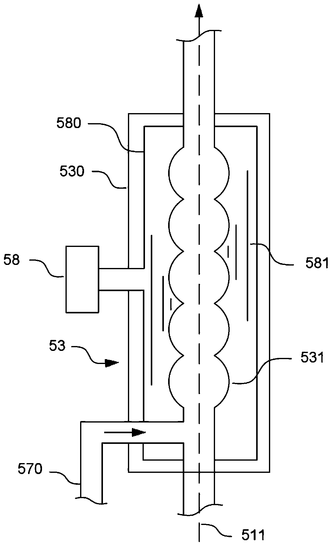
[0048] Such as figure 1 — Figure 5 As shown, the present invention provides a kind of high-efficiency treatment system of polluted gas source, comprising:

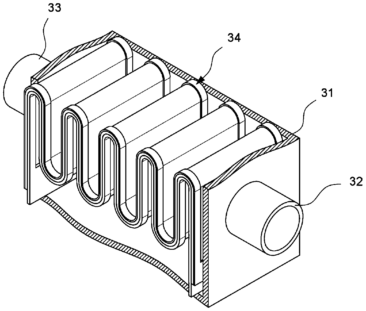
[0049] A low-temperature combustion unit 50, which is used to catalyze the low-temperature combustion of the polluted gas source 10;

[0050] An electron beam irradiation unit 5, which is arranged at the lower working station of the low-temperature combustion unit 50, for performing radiation irradiation treatment on the polluted gas source 10 after low-temperature combustion; and

[0051] A photocatalytic unit 6, which is arranged at the lower work station of the electron beam irradiation unit, for photocatalytic degradation of the polluted gas source 10 after radiation irradiation treatment;

[0052] Wherein, the el...


PUM

PropertyMeasurementUnit
thicknessaaaaaaaaaa

Abstract

The invention discloses an efficient treatment system of a polluting air source. The efficient treatment system includes a low-temperature combustion part, an electron beam irradiation part and an optical catalysis part, wherein the low-temperature combustion part is used to catalyze and combust the polluting air source at a low temperature; the electron beam irradiation part is arranged at a lower operation station below the low-temperature combustion part and used to perform irradiation treatment on the polluting air source combusted at a low temperature; the optical catalysis part is arranged at a lower operation station below the electron beam irradiation part and used to perform optical catalysis and degradation on the polluting air source subjected to irradiation treatment. According to the efficient treatment system disclosed by the invention, organic polluting air in the polluting air source can be catalyzed and combusted through the low-temperature combustion part; the polluting air source can be subjected to selective electron beam bombardment through the electron beam irradiation part, so that the target of desulfurization and denitrification of the polluting air sourcecan be achieved. The arranged optical catalysis part can further perform optical catalysis and degradation on air guided out of an irradiation reaction cavity, enhancing and ensuring impurity of airdischarged out by the polluting air source. The efficient treatment system of the invention has the advantages that the structure is compact, that the effect of purifying polluted air is great, and that the system is beneficial for popularization and utilization.

Description

technical field [0001] The invention relates to the technical field of waste gas treatment, in particular to an efficient treatment system for polluted gas sources. Background technique [0002] In the prior art, the treatment devices for polluted gas sources are relatively simple, and the purification of many polluted gases usually fails to achieve the expected effect, which is not conducive to environmental protection. In addition, the emission of polluted gas sources will not remain constant. In order to ensure that it can be completely processed, the purification equipment is usually made very large, which not only takes up a large equipment space, but also wastes part of the processing capacity of the purification equipment. , which increases the processing cost of the polluted air source; in addition, after the polluted air source is purified by a single treatment device, it is difficult to achieve complete purification, and if it is discharged into the air, it will st...

Claims


Application Information

Patent Timeline
Patent Type & Authority Applications(China)
IPC IPC(8): B01D53/86B01D53/74B01D53/60C01C1/242C01C1/18
CPCB01D53/86B01D53/74B01D53/60C01C1/242C01C1/185B01D2251/2062Y02A50/20
Inventor 董仕宏吴倩倩张世忠
Owner 苏州仕净科技股份有限公司
Learn More