
Compressor and air conditioning system

A technology for air conditioning systems and compressors, applied in compressors, refrigerators, mechanical equipment, etc., to solve problems such as inability to overcome and drop the exhaust pressure, backflow, compressor vibration, etc., to reduce the minimum cooling capacity, widen Operating range, effect of resolving surge

Pending Publication Date: 2019-08-27
GREE ELECTRIC APPLIANCES INC
View PDF0 Cites 2 Cited by
  • Summary
  • Abstract
  • Description
  • Claims
  • Application Information

AI Technical Summary

Problems solved by technology

[0003] For variable frequency centrifugal compressors and chillers, when the compressor operates at low speed, the suction capacity of the centrifugal impeller decreases, while the loss of refrigerant gas through the impeller channel increases to a certain extent, and the effective energy continues to decrease, resulting in The exhaust pressure cannot overcome the condensing pressure so that the impeller cannot discharge the gas normally, resulting in a decrease in the exhaust pressure. In this way, the gas in the high-pressure part after the impeller will flow back. After discharge, the air supply is still insufficient, the exhaust pressure will drop again, and backflow will occur again. This is repeated periodically, causing the compressor to produce severe vibration and noise and cannot work normally. This is the unique surge of centrifugal compressors. phenomenon, so there is a problem that the speed adjustment range of the frequency conversion magnetic levitation centrifugal compressor is limited

Method used


Image

  • Compressor and air conditioning system
  • Compressor and air conditioning system
  • Compressor and air conditioning system

Examples


Embodiment Construction

[0022] In order to make the object, technical solution and advantages of the present invention clearer, the present invention will be further described in detail below in conjunction with the accompanying drawings and embodiments. It should be understood that the specific embodiments described here are only used to explain the present invention, not to limit the present invention.

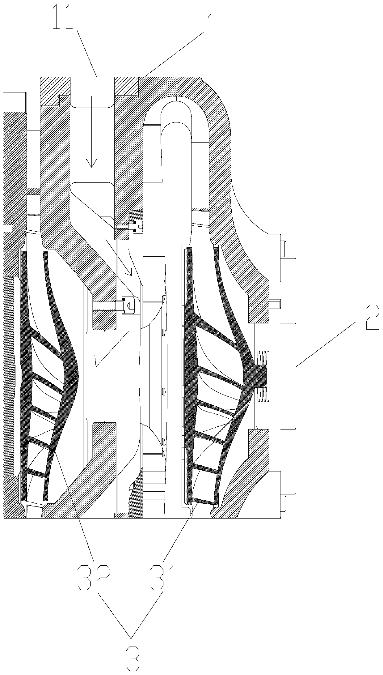
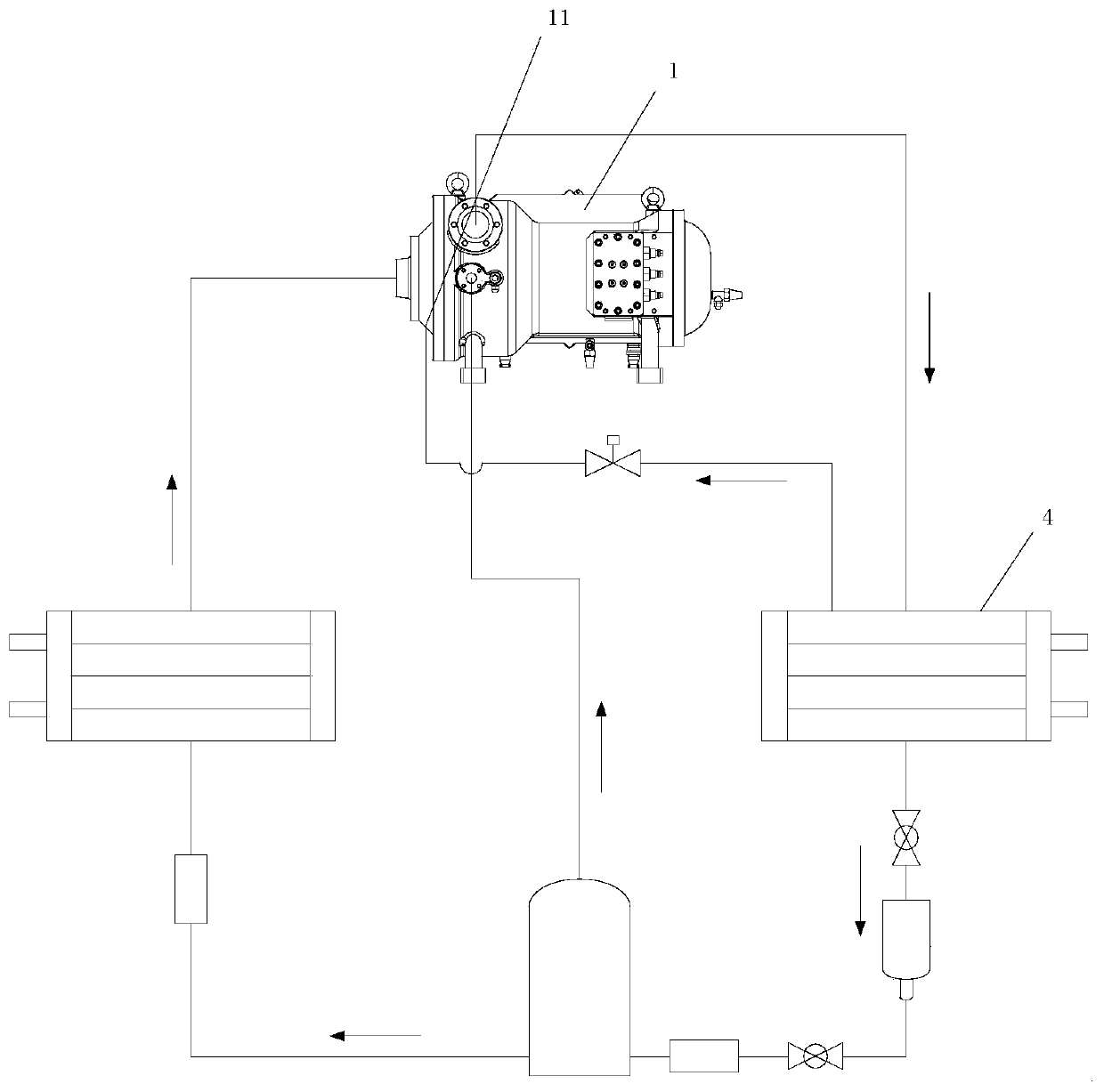
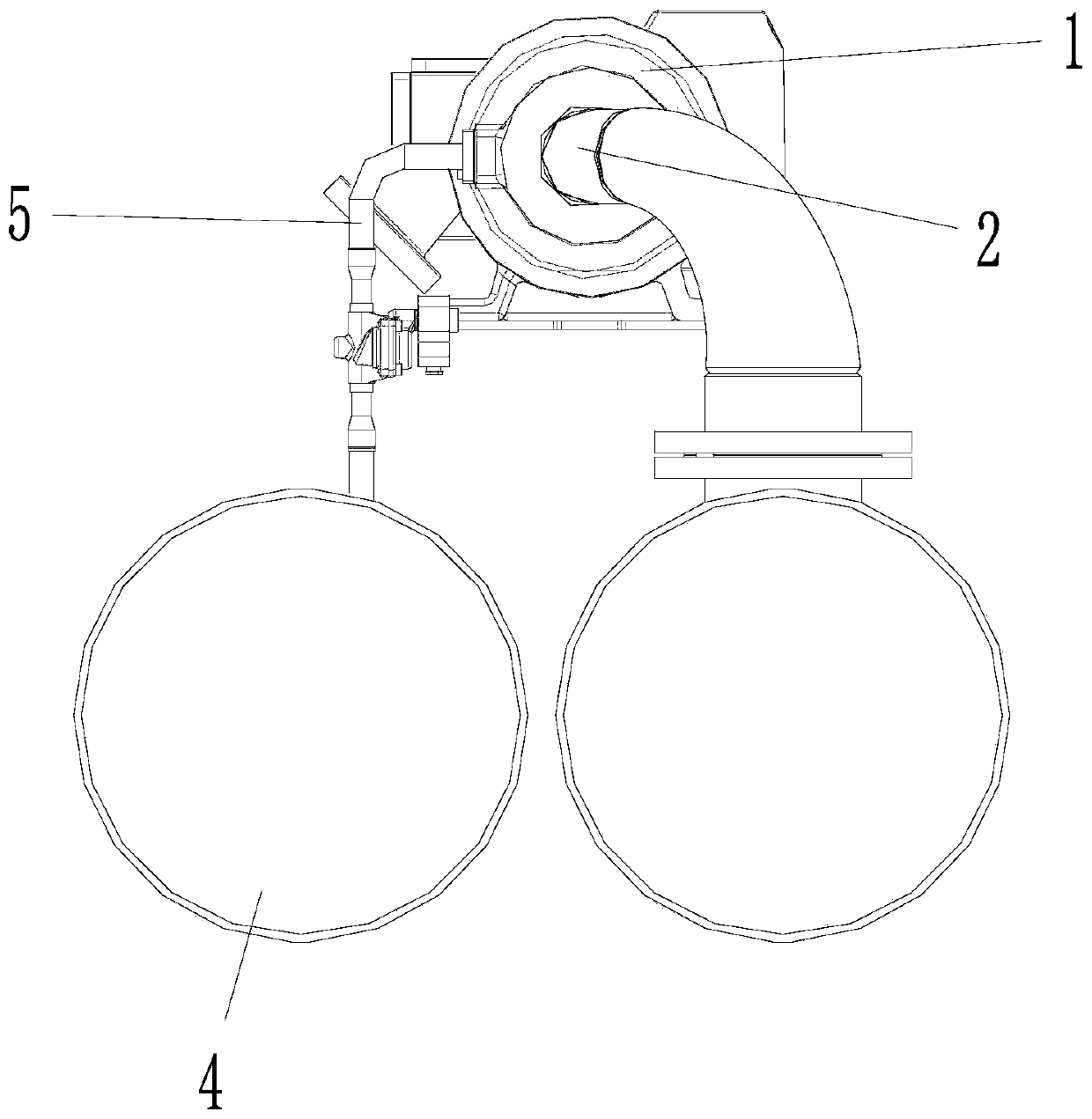
[0023] Such as Figure 1 to Figure 3 The shown compressor includes a casing 1, and the casing 1 is provided with a suction port 2, and at least two compression chambers 3 are formed inside the casing 1 in parallel and communicated in sequence, and all the compression chambers 3 The cavity 3 includes a primary compression cavity 31 and at least one secondary compression cavity 32 along the direction away from the suction port 2, and the housing 1 is provided with an air supply port 11, and the gas supply port 11 is connected to the corresponding The secondary compression chamber 32 communicates, an...


PUM


Abstract

The invention provides a compressor and an air conditioning system. The compressor comprises a shell, wherein an air suction opening is formed in the shell, at least two compression cavities which arearranged in parallel and communicate in sequence are formed in the shell, and each compression cavity comprises a primary compression cavity and at least one secondary compression cavity in the direction away from the air suction opening. According to the compressor and the air conditioning system, an air supply port is formed in the secondary compression chamber, and an external pressure supplystructure can be used for supplementing the pressure to the secondary compression chamber, so that the flow of gas in the secondary compression chamber is prevented from being reversed, the flow rateof refrigerant gas sucked into the secondary compression chamber at the low rotation speed is increased, the problem that the effective energy head of an impeller is reduced due to insufficient air suction amount under the low rotating speed of the centrifugal compressor is effectively solved, surge is avoided, the flow of the refrigerant flowing through a condenser is reduced, the minimum refrigerating capacity of the system is further reduced, and the running range of a centrifugal water chilling unit is widened.

Description

technical field [0001] The invention relates to the technical field of air treatment equipment, in particular to a compressor and an air conditioning system. Background technique [0002] The working principle of the compressor is to make the gas obtain kinetic energy by the high-speed rotating centrifugal impeller, and then throw the high-speed flowing gas that has obtained kinetic energy into the diffuser chamber to decelerate and pressurize, and convert the kinetic energy obtained by the gas into pressure energy, so as to improve the transport medium. For the purpose of high pressure, in order to obtain higher pressure, multi-stage impellers are generally purchased. The high-speed rotating primary impeller sucks low-temperature and low-pressure refrigerant gas, and then throws the gas into the primary diffuser to reduce the speed and increase the pressure, and then passes through the reflux device. It flows into the second-stage impeller, speeds up the second-stage impell...

Claims


Application Information

Patent Timeline
IPC IPC(8): F04D17/12F04D29/42F04D29/66F25B31/00F25B41/00F25B41/40
CPCF04D17/12F04D29/4206F04D29/668F04D29/667F25B31/00F25B41/00F25B2500/13F25B2500/12
Inventor 陈东红周江峰姜国璠章瑞
Owner GREE ELECTRIC APPLIANCES INC
Learn More