
Fault current determination method for droop control inverter

A technology of fault current and determination method, applied in the fields of instruments, electrical components, electrical digital data processing, etc., can solve problems such as reducing the safety and reliability of droop control inverters

Active Publication Date: 2019-08-23
ELECTRIC POWER RESEARCH INSTITUTE, CHINA SOUTHERN POWER GRID CO LTD +1
View PDF4 Cites 3 Cited by
  • Summary
  • Abstract
  • Description
  • Claims
  • Application Information

AI Technical Summary

Problems solved by technology

Therefore, in order to improve the reliability of the protection system and ensure the safety and reliability of the power electronic equipment in the droop control inverter, it is necessary to study and analyze its asymmetric fault characteristics. However, there is no one in the prior art A scheme for the transient characteristics of the fault current of droop-controlled inverters under asymmetrical fault types, which reduces the safety and reliability of droop-controlled inverters in grid-connected systems

Method used


Image

  • Fault current determination method for droop control inverter
  • Fault current determination method for droop control inverter
  • Fault current determination method for droop control inverter

Examples


Embodiment Construction

[0068] The core of the invention is to provide a method for determining the fault current of the droop control inverter, which improves the safety and reliability of the droop control inverter in the grid-connected system.

[0069] In order to make the purpose, technical solutions and advantages of the embodiments of the present invention clearer, the technical solutions in the embodiments of the present invention will be clearly and completely described below in conjunction with the drawings in the embodiments of the present invention. Obviously, the described embodiments It is a part of embodiments of the present invention, but not all embodiments. Based on the embodiments of the present invention, all other embodiments obtained by persons of ordinary skill in the art without making creative efforts belong to the protection scope of the present invention.

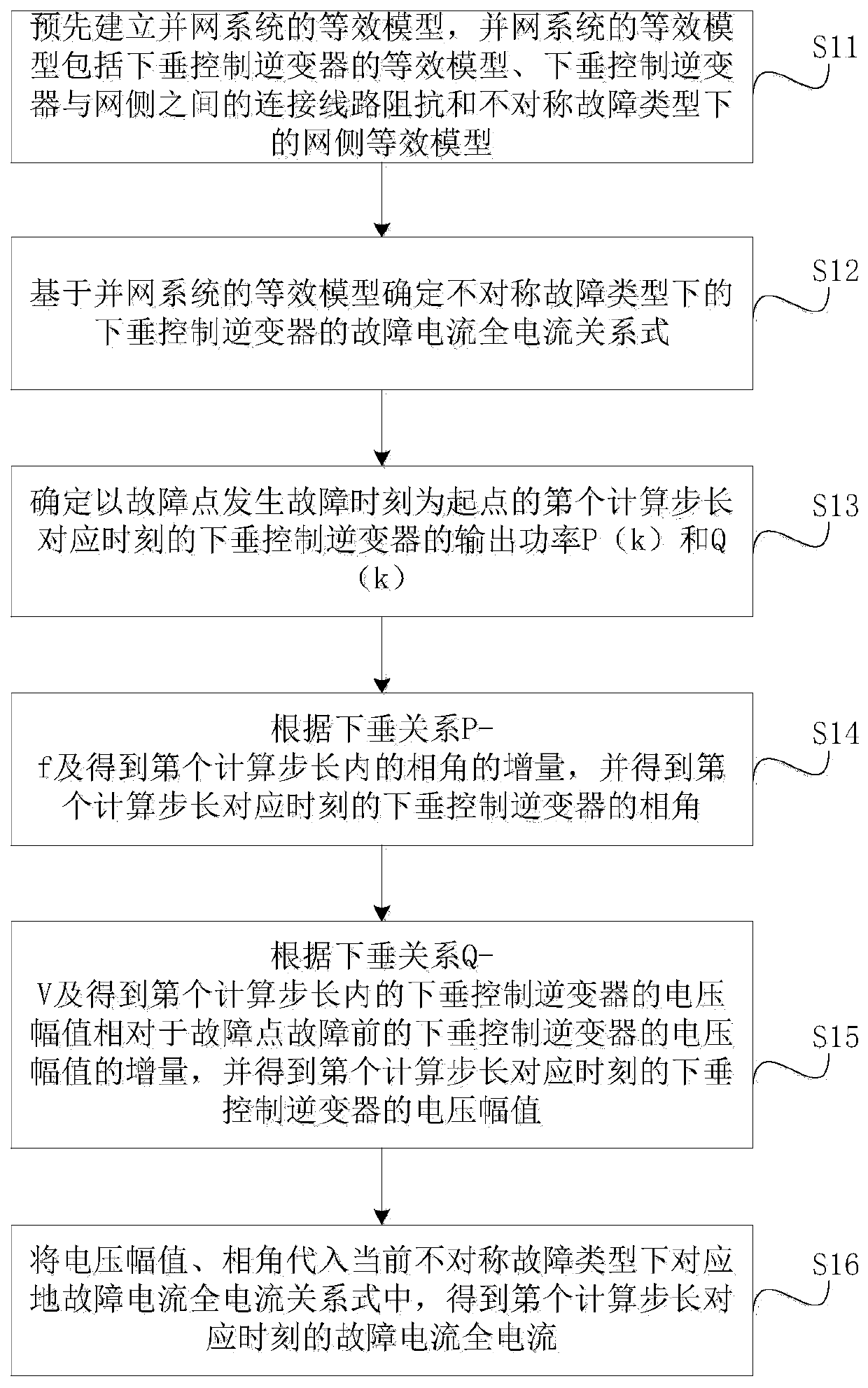
[0070] Please refer to figure 1 , figure 1 A flow chart of a method for determining the fault current of a droop cont...


PUM


Abstract

The invention discloses a fault current determination method for a droop control inverter. The method comprises the steps of pre-establishing a grid-connected system equivalent model comprising a droop control inverter under an asymmetric fault type, obtaining a fault current total current relational expression of the droop control inverter under the asymmetric fault type based on the grid-connected system equivalent model; when the fault current is calculated subsequently, adopting a fault current iteration algorithm in combination with a fault current total current relational expression to eliminate strong coupling between power and voltage; and obtaining fault current full current in full-scale time; in this way, the characteristics (including transient characteristics) of the fault current of the droop control inverter at any time under the asymmetric fault type can be obtained; guidance is provided for a fault ride-through strategy of the droop control inverter, guidance is also provided for micro-grid relay protection setting containing the droop control inverter, and the safety and reliability of the droop control inverter in a grid-connected system are improved.

Description

technical field [0001] The invention relates to the technical field of fault analysis, in particular to a method for determining a fault current of a droop control inverter. Background technique [0002] In recent years, based on the technological progress of power electronic systems, the concept of microgrid has emerged as the times require. As an autonomous system that can realize self-control and management, the microgrid can effectively absorb the output of intermittent and distributed renewable energy generation while improving the reliability of power supply for users. Usually, power electronic devices such as inverters are used as the interface of distributed energy in microgrids. For these microgrids with high penetration of renewable energy, the dynamic characteristics of the grid-connected system are mainly determined by the control scheme adopted by the microsource itself and the inverter. Among the control schemes adopted by inverters, the droop control strateg...

Claims


Application Information

Patent Timeline
IPC IPC(8): G06F17/50H02H7/28
CPCH02H7/28G06F30/20
Inventor 喻磊谈赢杰胡洋黄安迪马溪原雷金勇袁智勇陈柔伊
Owner ELECTRIC POWER RESEARCH INSTITUTE, CHINA SOUTHERN POWER GRID CO LTD
Learn More